AUTOMATIC TRANSAXLE ASSEMBLY (for 1AZ-FE) INSTALLATION

-
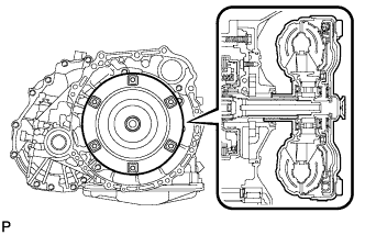
INSTALL TORQUE CONVERTER ASSEMBLY
-
Mesh the splines of the input shaft and turbine runner.
-
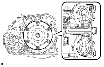
Mesh the splines of the stator shaft and stator while turning the torque converter.
Tech Tips
If the stator shaft splines are difficult to mesh with the stator splines, move the torque converter back approximately 10 mm (0.394 in.) and mesh the splines while rotating the torque converter.
-
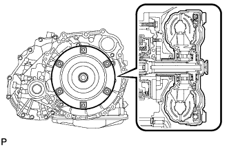
Turn the torque converter to insert the key of the oil pump drive gear into the slot on the torque converter.
-
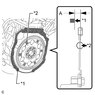
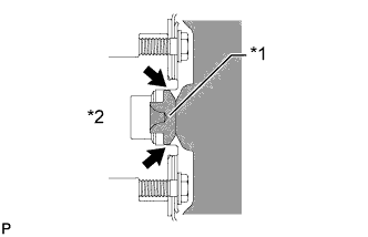
Using a vernier caliper and straightedge, measure dimension A between the transaxle fitting surface of the engine*1 and the converter clutch fitting surface of the drive plate*2. (#)
-
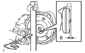
Using a vernier caliper and straightedge, measure dimension B shown in the illustration. Check that B is greater than A (measured in (#)).
Standard dimension B A + 1.0 mm (0.0394 in.) or more Note
-
Be sure to subtract the thickness of the straightedge.
-
If the transaxle is installed to the engine with the torque converter not sufficiently inserted, the torque converter may be damaged.
-
-
-
INSTALL TRANSMISSION CONTROL CABLE SUPPORT
-
Install the transmission control cable support with the bolt.
- Torque:
- 5.0 N*m { 51 kgf*cm, 44 in.*lbf }
-
-
INSTALL WIRE HARNESS CLAMP BRACKET
-
Install the bracket with the bolt.
- Torque:
- 13 N*m { 130 kgf*cm, 9 ft.*lbf }
-
-
INSTALL SPEEDOMETER DRIVEN HOLE COVER SUB-ASSEMBLY
-
Coat a new O-ring with ATF WS and install it to the hole cover.
-
Install the hole cover to the transaxle case with the bolt.
- Torque:
- 5.5 N*m { 56 kgf*cm, 49 in.*lbf }
-
-
INSTALL NO. 1 TRANSMISSION CONTROL CABLE BRACKET
-
Install the No. 1 transmission control cable bracket with the 2 bolts.
- Torque:
- 12 N*m { 122 kgf*cm, 9 ft.*lbf }
-
-
INSTALL TRANSMISSION OIL FILLER TUBE SUB-ASSEMBLY
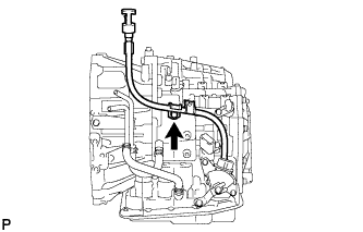
-
Coat a new O-ring with ATF WS and install it to the oil filler tube sub-assembly.
-
Install the oil filler tube to the automatic transaxle with the bolt.
- Torque:
- 5.5 N*m { 56 kgf*cm, 49 in.*lbf }
-
Install the ATF dipstick.
-
-
INSTALL AUTOMATIC TRANSAXLE ASSEMBLY
-
Apply clutch spline grease to the round of the crankshaft contact surface with the torque converter centerpiece.
Clutch spline grease Toyota Genuine Clutch Spline Grease or equivalent Maximum spread About 1 g (0.0353 oz) Text in Illustration *1 Torque Convertor Centerpiece *2 Crankshaft -
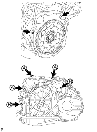
Install the automatic transaxle to the engine with the 5 bolts.
- Torque:
- for bolt A
- 64 N*m { 652 kgf*cm, 47 ft.*lbf }
- for bolt B
- 46 N*m { 469 kgf*cm, 34 ft.*lbf }
Note
Confirm that 2 knock pins are on the transaxle fitted surface of the engine block before transaxle installation.
-
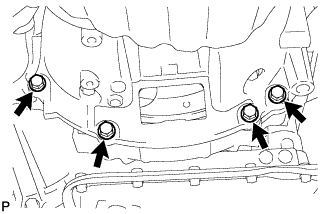
Install the 4 lower side mounting bolts.
- Torque:
- 44 N*m { 448 kgf*cm, 32 ft.*lbf }
-
-
INSTALL DRIVE PLATE AND TORQUE CONVERTER SETTING BOLT
-
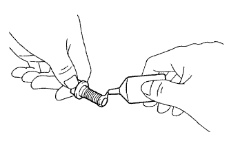
Apply a few drops of adhesive to 2 or 3 threads of the 6 torque converter setting bolts tips.
Adhesive Toyota Genuine Adhesive 1324, Three Bond 1324 or equivalent -
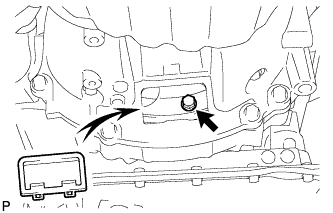
Turn the crankshaft to gain access to the installation locations of the 6 torque converter setting bolts and install each bolt while holding the crankshaft pulley bolt with a wrench.
- Torque:
- 41 N*m { 418 kgf*cm, 30 ft.*lbf }
Note
Install the black bolt first, and then the 5 silver bolts.
-
Install the flywheel housing under cover.
-
-
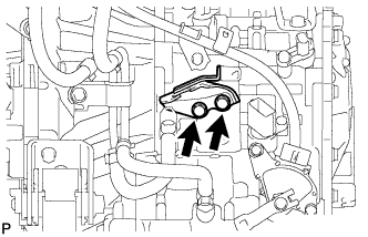
INSTALL OIL COOLER TUBE SUB-ASSEMBLY
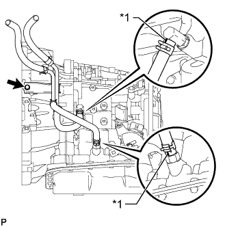
Text in Illustration *1 White Paint Mark
-
Install the oil cooler tube with the bolt and connect the 2 oil cooler hoses.
- Torque:
- 12 N*m { 117 kgf*cm, 8 ft.*lbf }
Note
Make sure the paint marks and pinching portion of each clip are facing the direction shown in the illustration.
-
-
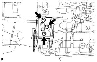
INSTALL ENGINE MOUNTING BRACKET LH
-
Install the engine mounting bracket LH to the automatic transaxle with the 3 bolts.
- Torque:
- 64 N*m { 653 kgf*cm, 47 ft.*lbf }
-
-
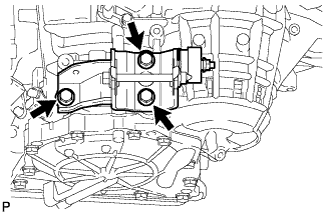
INSTALL REAR ENGINE MOUNTING BRACKET
-
Install the mounting bracket to the automatic transaxle with the 3 bolts.
- Torque:
- 45 N*m { 459 kgf*cm, 33 ft.*lbf }
-
-
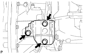
INSTALL FRONT ENGINE MOUNTING BRACKET
-
Install the mounting bracket to the automatic transaxle with the 3 bolts.
- Torque:
- 64 N*m { 653 kgf*cm, 47 ft.*lbf }
-
-
INSTALL GROUND CABLE
-
Install the ground cable with the bolt and attach the harness clamp.
- Torque:
- 26 N*m { 260 kgf*cm, 19 ft.*lbf }
-
-
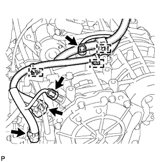
CONNECT WIRE HARNESS
-
Connect the 2 speed sensor connectors.
-
Connect the transaxle wire connector.
-
Connect the park/neutral position switch connector.
-
Attach the 3 wire harness clamps.
-
-
INSTALL STARTER ASSEMBLY
-
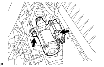
Install the starter with the 2 bolts.
- Torque:
- 37 N*m { 380 kgf*cm, 27 ft.*lbf }
-
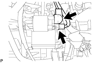
Connect the starter connector.
-
Connect the starter wire with the nut and close the terminal cap.
- Torque:
- 9.8 N*m { 100 kgf*cm, 87 in.*lbf }
-
-
INSTALL ENGINE ASSEMBLY WITH TRANSAXLE
-
Install the engine with transaxle Click here.
-
-
ADD AUTOMATIC TRANSAXLE FLUID
Fluid type Toyota Genuine ATF WS -
INSPECT TRANSAXLE FLUID LEVEL
-
Inspect the transaxle fluid level Click here.
-
-
INSPECT FOR EXHAUST GAS LEAK
-
INSPECT SHIFT LEVER POSITION
-
When moving the shift lever from P to R with the ignition switch ON and the brake pedal depressed, make sure that the shift lever moves smoothly and correctly into position.
-
Start the engine and make sure that the vehicle moves forward after moving the shift lever from N to D and moves in reverse after moving the shift lever to R. If the operation cannot be performed as specified, inspect the park/neutral position switch assembly and check the shift lever assembly installation condition.
-
-
ADJUST SHIFT LEVER POSITION
-
Remove the console box assembly Click here.
-
Apply the parking brake and move the shift lever to N.
-
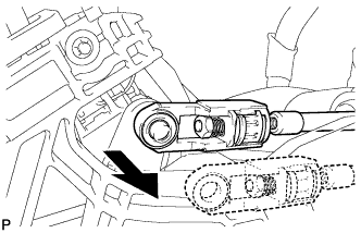
Disconnect the end of the transmission control cable assembly from the shift lever assembly.
-
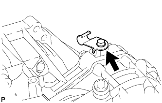
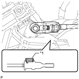
Text in Illustration *1 Stopper *2 Nut Pull out the stopper of the transmission control cable.
Note
Do not remove the stopper. If the stopper is removed, reinstall it to its original position.
-
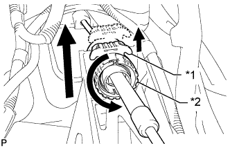
Rotate the nut counterclockwise approximately 180° and, while holding the nut in that position, disconnect the transmission control cable from the shift lever retainer.
Note
Do not over-rotate the nut as it will come off the internal spring and the transmission control cable will not be reusable.
-
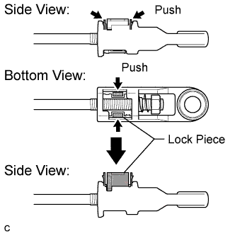
Push the 2 claws together at the top of the transmission control cable lock piece. While holding the 2 claws together, push the 2 lugs on the bottom of the lock piece toward each other and upward to pull out the lock piece.
-
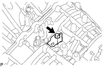
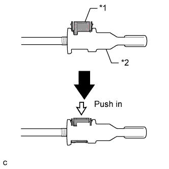
Turn the nut of the transmission control cable 180° counterclockwise. While holding the nut in place, push in the stopper until the stopper clicks twice.
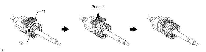
Text in Illustration *1 Stopper *2 Nut -
Install the outer part of the transmission control cable to the shift lever retainer. Check that the spring is positioned at "A" and push in the stopper.
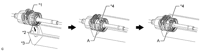
Text in Illustration *1 Stopper *3 Shift Lever Retainer *2 Nut *4 Spring Tech Tips
If the stopper cannot be pushed in, slightly turn the nut clockwise and then push in the stopper again.
-
Text in Illustration *1 Lock Piece Connect the end of the cable to the shift lever assembly.
Note
-
Make sure that the lock piece is pulled up.
-
Push on the end of the cable all the way to the base of the pin.
-
-
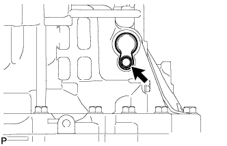
Text in Illustration *1 Lock Piece *2 Adjuster Case Push the lock piece into the adjuster case.
Note
Securely push in the lock piece until it locks.
-
After adjusting the shift lever position, check the operation and function of the shift lever. If there is a problem, adjust the position again.
-
Install the console box Click here.
-
-
RESET MEMORY
Tech Tips
Perform Reset Memory (AT initialization) when replacing the automatic transaxle assembly Click here.