TRANSMISSION CONTROL CABLE INSTALLATION

-
INSTALL TRANSMISSION CONTROL CABLE ASSEMBLY
Note
Before installing the transmission control cable assembly, check that the park/neutral position switch and shift lever are in neutral.
-
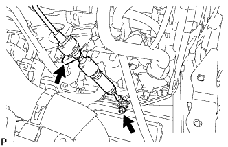
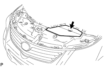
Put the transmission control cable into the cabin and install the transmission control cable with the 2 nuts.
- Torque:
- 5.0 N*m { 51 kgf*cm, 44 in.*lbf }
-
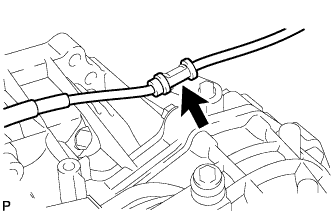
Connect the transmission control cable support with the bolt.
- Torque:
- 5.0 N*m { 51 kgf*cm, 44 in.*lbf }
-
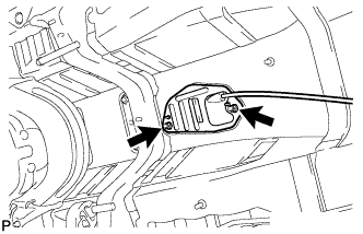
Connect the transmission control cable to the transmission control cable support.
-
Connect the transmission control cable to the bracket with a new clip.
-
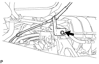
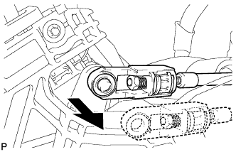
Connect the transmission control cable assembly to the control shaft lever with the nut.
- Torque:
- 12 N*m { 122 kgf*cm, 9 ft.*lbf }
-
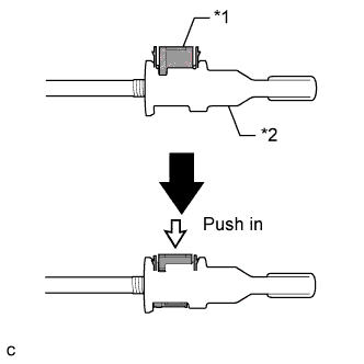
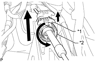
Turn the nut of the transmission control cable 180° counterclockwise. While holding the nut in place, push in the stopper until the stopper clicks twice.
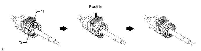
Text in Illustration *1 Stopper *2 Nut -
Install the outer part of the transmission control cable to the shift lever retainer. Check that the spring is positioned at "A" and push in the stopper.
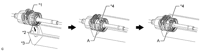
Text in Illustration *1 Stopper *3 Shift Lever Retainer *2 Nut *4 Spring Tech Tips
If the stopper cannot be pushed in, slightly turn the nut clockwise and then push in the stopper again.
-
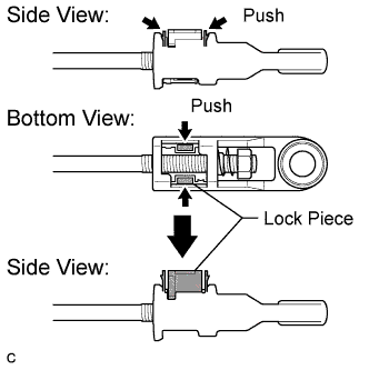
Push the 2 claws together at the top of the transmission control cable lock piece. While holding the 2 claws together, push the 2 lugs on the bottom of the lock piece toward each other and upward to pull out the lock piece.
-
Text in Illustration *1 Lock Piece Connect the end of the cable to the shift lever assembly.
Note
-
Make sure that the lock piece is pulled up.
-
Push on the end of the cable all the way to the base of the pin.
-
-
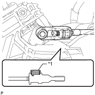
Text in Illustration *1 Lock Piece *2 Adjuster Case Push the lock piece into the adjuster case.
Note
Securely push in the lock piece until it locks.
-
-
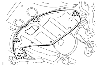
INSTALL FRONT FLOOR NO. 1 HEAT INSULATOR
-
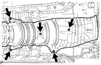
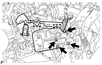
Install the heat insulator with the 5 nuts.
- Torque:
- 5.5 N*m { 56 kgf*cm, 49 in.*lbf }
-
-
INSTALL FRONT EXHAUST PIPE ASSEMBLY (for 1AZ-FE)
-
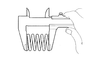
Using a vernier caliper, measure the free length of the compression spring.
Minimum length 41.5 mm (1.63 in.) If the free length is less than the minimum, replace the compression spring.
-
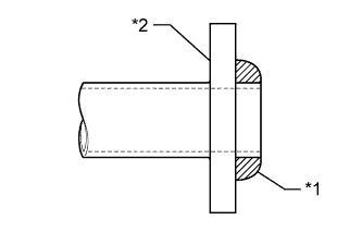
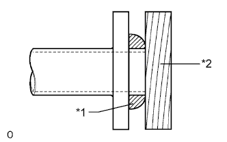
Text in Illustration *1 Gasket *2 Exhaust Manifold Install a new gasket to the exhaust manifold.
Note
-
Be sure to install the gasket in the correct direction.
-
Do not reuse the gasket.
-
Do not damage the gasket.
-
-
Install the straight screw plug.
- Torque:
- 43 N*m { 438 kgf*cm, 32 ft.*lbf }
-
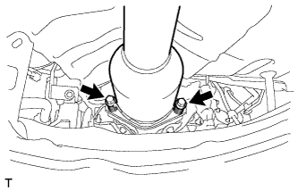
Install the front exhaust pipe with the 2 compression springs and 2 bolts.
- Torque:
- 43 N*m { 438 kgf*cm, 32 ft.*lbf }
-
-
INSTALL CENTER EXHAUST PIPE ASSEMBLY (for 1AZ-FE)
-
Using a vernier caliper, measure the free length of the compression spring.
Minimum length 38.5 mm (1.52 in.) If the free length is less than the minimum, replace the compression spring.
-
Text in Illustration *1 Gasket *2 Exhaust Pipe Assembly Install a new gasket to the center exhaust pipe assembly.
Note
-
Be sure to install the gasket in the correct direction.
-
Do not reuse the gasket.
-
Do not damage the gasket.
-
-
Connect the 4 exhaust pipe supports to install the tailpipe.
-
Install the 2 compression springs and 2 bolts.
- Torque:
- 43 N*m { 438 kgf*cm, 32 ft.*lbf }
-
-
INSTALL FRONT EXHAUST PIPE ASSEMBLY (for 3ZR-FE)
-
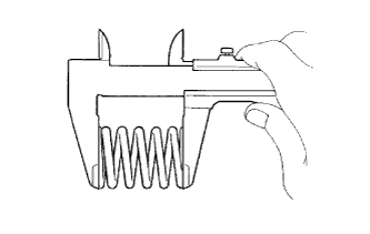
Using a vernier caliper, measure the free length of the compression springs.
Minimum Free Length 41.5 mm (1.63 in.) If the free length is less than the minimum, replace the compression spring.
-
Text in Illustration *1 Gasket *2 Wooden Block Using a plastic-faced hammer and wooden block, tap in a new gasket until its surface is flush with the exhaust manifold.
Note
-
Be sure to install the gasket so that it faces the correct direction.
-
Do not reuse the gasket.
-
Do not damage the gasket.
-
When connecting the exhaust pipe, do not push in the gasket with the exhaust pipe.
-
-
Install the 2 exhaust pipe supports, and then install the front exhaust pipe assembly with the 2 bolts and 2 compression springs.
- Torque:
- 43 N*m { 438 kgf*cm, 32 ft.*lbf }
-
-
CONNECT HEATED OXYGEN SENSOR CONNECTOR (for 3ZR-FE)
-
INSTALL NO. 2 ENGINE UNDER COVER (for 3ZR-FE)
-
Install the under cover with the 4 clips.
-
-
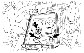
INSTALL AIR CLEANER CASE SUB-ASSEMBLY (for 1AZ-FE)
-
Install the air cleaner case with the 3 bolts.
- Torque:
- 7.0 N*m { 71 kgf*cm, 62 in.*lbf }
-
Connect the engine wire.
-
-
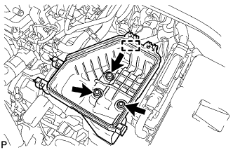
INSTALL AIR CLEANER CASE SUB-ASSEMBLY (for 3ZR-FE)
-
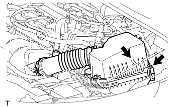
Install the air cleaner case with the 3 bolts.
- Torque:
- 7.0 N*m { 71 kgf*cm, 62 in.*lbf }
-
Attach the wire harness clamp to the air cleaner case.
-
-
INSTALL AIR CLEANER CAP AND HOSE (for 1AZ-FE)
-
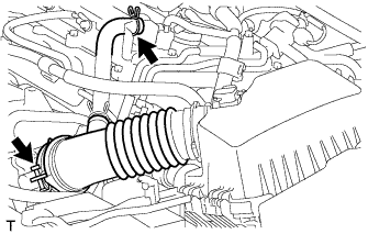
Insert the hinge part of the air cleaner cap and hose into the air cleaner case, and then fasten the 3 hook clamps.
-
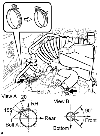
Align the matchmarks of the No. 1 air cleaner hose and throttle body. Then connect the No. 1 air cleaner hose to the throttle body and push apart the tabs of the No. 1 air cleaner hose clamp.
Note
Make sure that the hose clamp is at the correct angle.
-
Connect the No. 2 fuel vapor feed hose to the air cleaner hose.
-
Connect the No. 2 ventilation hose to the air cleaner hose.
-
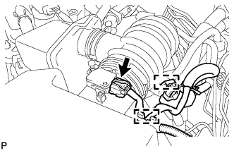
Connect the purge VSV.
-
Connect the wire harness and mass air flow meter connector.
-
-
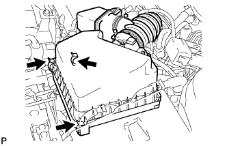
INSTALL AIR CLEANER CAP AND HOSE (for 3ZR-FE)
-
Connect the air cleaner cap with the band.
-
Connect the ventilation hose.
-
Connect the 2 clamps.
-
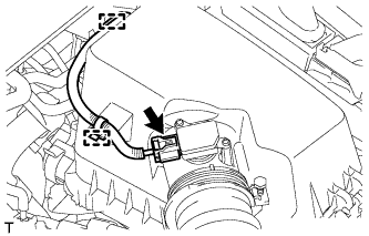
Attach the wire harness to the 2 clamps.
-
Connect the mass air flow meter connector.
-
-
INSTALL BATTERY CARRIER
-
Install the battery carrier with the 4 bolts.
- Torque:
- 19 N*m { 194 kgf*cm, 14 ft.*lbf }
-
Attach the 2 wire harness clamps.
-
-
INSTALL BATTERY
-
Install the battery tray.
-
Install the battery.
-
Install the battery clamp with the bolt and tighten the nut.
- Torque:
- for bolt
- 17 N*m { 168 kgf*cm, 12 ft.*lbf }
- for nut
- 3.5 N*m { 36 kgf*cm, 31 in.*lbf }
-
Connect the cable to the positive (+) battery terminal.
- Torque:
- 5.4 N*m { 55 kgf*cm, 48 in.*lbf }
-
-
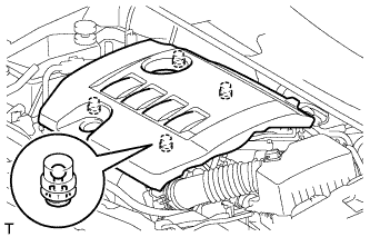
INSTALL NO. 1 ENGINE COVER SUB-ASSEMBLY (for 1AZ-FE)
-
Install the cover with the 2 nuts.
- Torque:
- 9.0 N*m { 92 kgf*cm, 80 in.*lbf }
-
-
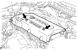
INSTALL NO. 2 CYLINDER HEAD COVER (for 3ZR-FE)
-
Attach the 4 clips to install the cover.
Note
-
Be sure to attach the clips securely.
-
Do not apply excessive force or hit the cover to attach the clips. This may cause the cover to break.
-
-
-
CONNECT CABLE TO NEGATIVE BATTERY TERMINAL
Note
When disconnecting the cable, some systems need to be initialized after the cable is reconnected Click here.
-
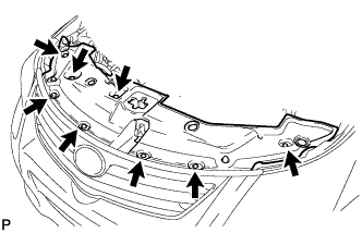
INSTALL RADIATOR SUPPORT OPENING COVER
-
Install the radiator support opening cover with the 8 clips.
-
-
INSTALL ENGINE ROOM SIDE COVER
-
Install the engine room side cover with the clip.
-
-
INSPECT SHIFT LEVER POSITION
-
When moving the shift lever from P to R with the ignition switch ON and the brake pedal depressed, make sure that the shift lever moves smoothly and correctly into position.
-
Start the engine and make sure that the vehicle moves forward after moving the shift lever from N to D and moves in reverse after moving the shift lever to R. If the operation cannot be performed as specified, inspect the park/neutral position switch assembly and check the shift lever assembly installation condition.
-
-
ADJUST SHIFT LEVER POSITION
-
Remove the console box assembly Click here.
-
Apply the parking brake and move the shift lever to N.
-
Disconnect the end of the transmission control cable assembly from the shift lever assembly.
-
Text in Illustration *1 Stopper *2 Nut Pull out the stopper of the transmission control cable.
Note
Do not remove the stopper. If the stopper is removed, reinstall it to its original position.
-
Rotate the nut counterclockwise approximately 180° and, while holding the nut in that position, disconnect the transmission control cable from the shift lever retainer.
Note
Do not over-rotate the nut as it will come off the internal spring and the transmission control cable will not be reusable.
-
Push the 2 claws together at the top of the transmission control cable lock piece. While holding the 2 claws together, push the 2 lugs on the bottom of the lock piece toward each other and upward to pull out the lock piece.
-
Turn the nut of the transmission control cable 180° counterclockwise. While holding the nut in place, push in the stopper until the stopper clicks twice.
Text in Illustration *1 Stopper *2 Nut -
Install the outer part of the transmission control cable to the shift lever retainer. Check that the spring is positioned at "A" and push in the stopper.
Text in Illustration *1 Stopper *3 Shift Lever Retainer *2 Nut *4 Spring Tech Tips
If the stopper cannot be pushed in, slightly turn the nut clockwise and then push in the stopper again.
-
Text in Illustration *1 Lock Piece Connect the end of the cable to the shift lever assembly.
Note
-
Make sure that the lock piece is pulled up.
-
Push on the end of the cable all the way to the base of the pin.
-
-
Text in Illustration *1 Lock Piece *2 Adjuster Case Push the lock piece into the adjuster case.
Note
Securely push in the lock piece until it locks.
-
After adjusting the shift lever position, check the operation and function of the shift lever. If there is a problem, adjust the position again.
-
Install the console box Click here.
-
-
INSTALL CONSOLE BOX ASSEMBLY
-
Install the console box assembly Click here
-