OIL COOLER INSTALLATION

-
INSTALL NO. 2 OIL COOLER TUBE SUB-ASSEMBLY
-
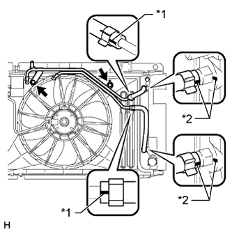
Text in Illustration *1 White Paint Mark *2 Yellow Paint Mark Connect the No. 3 oil cooler inlet hose and No. 3 oil cooler outlet hose to the No. 2 oil cooler tube.
Note
Make sure the pinching portion of each clip is facing the direction shown in the illustration and the paint marks are aligned as shown in the illustration.
-
Install the No. 2 oil cooler tube sub-assembly to the radiator with the 2 bolts.
- Torque:
- 5.5 N*m { 56 kgf*cm, 49 in.*lbf }
-
Connect the No. 3 oil cooler inlet hose and No. 3 oil cooler outlet hose to the radiator.
Note
Make sure the pinching portion of each clip is facing the direction shown in the illustration and the paint marks are aligned as shown in the illustration.
-
-
INSTALL NO. 1 OIL COOLER TUBE SUB-ASSEMBLY
-
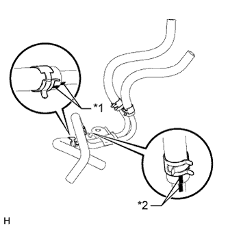
Text in Illustration *1 Yellow Paint Mark *2 Blue Paint Mark Connect the No. 1 oil cooler inlet hose, No. 1 oil cooler outlet hose, No. 2 oil cooler inlet hose and No. 2 oil cooler outlet hose to the No. 1 oil cooler tube.
Note
Make sure the pinching portion of each clip is facing the direction shown in the illustration and the paint marks are aligned as shown in the illustration.
-
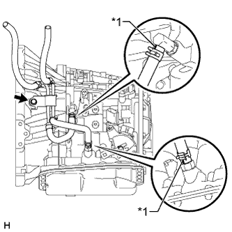
Text in Illustration *1 Yellow Paint Mark Install the No. 1 oil cooler tube sub-assembly with the bolt.
- Torque:
- 12 N*m { 117 kgf*cm, 8 ft.*lbf }
-
Connect the No. 1 oil cooler inlet hose and No. 1 oil cooler outlet hose to the automatic transaxle.
Note
Make sure the paint marks and pinching portion of each clip are facing the direction shown in the illustration.
-
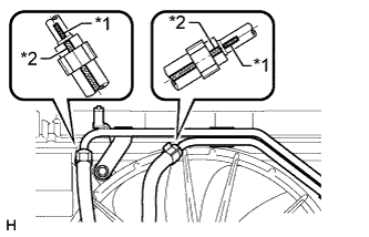
Text in Illustration *1 Yellow Paint Mark *2 Printed Mark Connect the No. 2 oil cooler inlet hose and No. 2 oil cooler outlet hose to the No. 2 oil cooler tube.
Note
Make sure the pinching portion of each clip is facing the direction shown in the illustration and the paint marks are aligned as shown in the illustration.
-
-
INSTALL NO. 1 ENGINE UNDER COVER
-
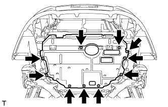
Install the under cover with the 10 clips.
-
-
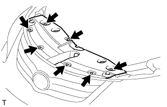
INSTALL FRONT LOWER BUMPER ABSORBER
-
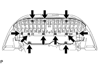
Install the front lower bumper absorber with the 8 bolts and 3 screws.
-
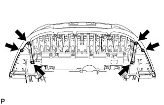
Install the 2 screws and 4 bolts.
-
-
INSTALL BATTERY CARRIER
-
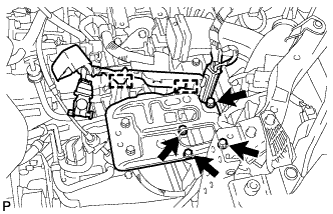
Install the battery carrier with the 4 bolts.
- Torque:
- 19 N*m { 194 kgf*cm, 14 ft.*lbf }
-
Attach the 2 wire harness clamps.
-
-
INSTALL BATTERY
-
Install the battery tray.
-
Install the battery.
-
Install the battery clamp with the bolt and tighten the nut.
- Torque:
- for bolt
- 17 N*m { 168 kgf*cm, 12 ft.*lbf }
- for nut
- 3.5 N*m { 36 kgf*cm, 31 in.*lbf }
-
Connect the cable to the positive (+) battery terminal.
- Torque:
- 5.4 N*m { 55 kgf*cm, 48 in.*lbf }
-
-
CONNECT CABLE TO NEGATIVE BATTERY TERMINAL
Note
When disconnecting the cable, some systems need to be initialized after the cable is reconnected Click here.
-
ADD AUTOMATIC TRANSAXLE FLUID
Fluid type Toyota Genuine ATF WS -
INSPECT AUTOMATIC TRANSAXLE FLUID LEVEL
-
Inspect the transaxle fluid level Click here.
-
-
INSTALL RADIATOR SUPPORT OPENING COVER
-
Install the radiator support opening cover with the 7 clips.
-