AUTOMATIC TRANSAXLE UNIT INSPECTION

-
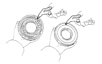
INSPECT AUTOMATIC TRANSAXLE OIL PAN SUB-ASSEMBLY
-
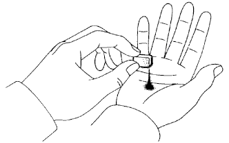
Remove the magnets and use them to collect any steel chips. Examine the chips and particles in the pan and on the magnet to determine what type of wear has occurred in the transaxle.
Steel (magnetic): bearing, gear and plate wear
Brass (non-magnetic): bush wear
-
-
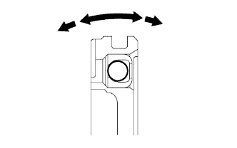
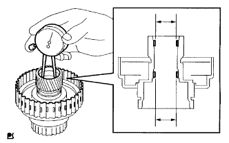
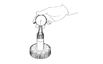
INSPECT INPUT SHAFT END PLAY
-
Secure the transaxle case with the oil pump side facing up.
-
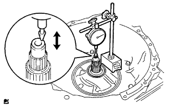
Using a dial indicator, measure the input shaft end play.
Standard end play 0.26 to 1.25 mm (0.0103 to 0.0492 in.)
-
-
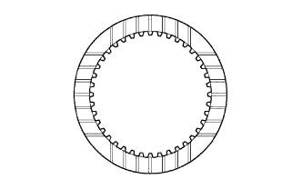
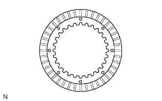
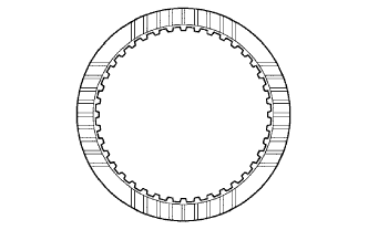
INSPECT FORWARD MULTIPLE DISC CLUTCH CLUTCH DISC
-
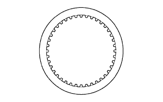
Check to see if the sliding surfaces of the discs, plates and flange are worn or burnt.
If necessary, replace them.
Note
-
If the lining of a disc is peeling off or discolored, replace all the discs.
-
Before assembling new discs, soak them in ATF WS for at least 15 minutes.
-
-
-
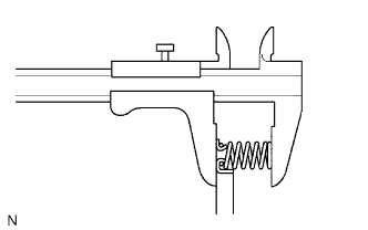
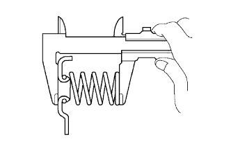
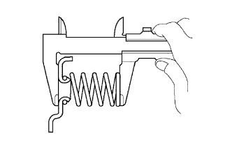
INSPECT FORWARD CLUTCH RETURN SPRING SUB-ASSEMBLY
-
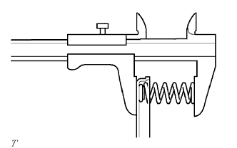
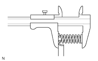
Using a vernier caliper, measure the free length of the spring together with the spring seat.
Standard free length 28.23 mm (1.11 in.)
-
-
INSPECT FORWARD CLUTCH PISTON SUB-ASSEMBLY
-
Shake the piston to check that the check ball is not stuck.
-
Check that the valve does not leak when applying low compressed air (392 kPa, 4.0 kgf/cm2, 57 psi).
-
-
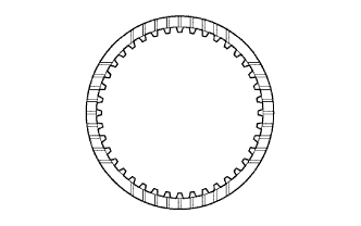
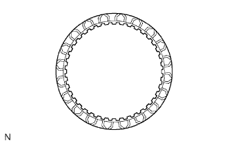
INSPECT NO. 1 UNDERDRIVE CLUTCH DISC
-
Check to see if the sliding surfaces of the discs, plates and flange are worn or burnt. If necessary, replace them.
Note
-
If the lining of a disc is peeling off or discolored, or even if a part of the printed mark is defaced, replace all the discs.
-
Before assembling new discs, soak them in ATF for at least 15 minutes.
-
-
-
INSPECT UNDERDRIVE CLUTCH RETURN SPRING SUB-ASSEMBLY
-
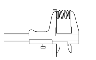
Using a vernier caliper, measure the free length of the spring together with the spring seat.
Standard free length 17.14 mm (0.675 in.)
-
-
INSPECT UNDERDRIVE CLUTCH DRUM SUB-ASSEMBLY
-
Using a caliper gauge, measure the inside diameter of the underdrive clutch drum bush.
Standard inside diameter 32.56 to 32.58 mm (1.282 to 1.283 in.) Maximum inside diameter 32.63 mm (1.285 in.) If the inside diameter is more than the maximum, replace the underdrive clutch drum sub-assembly.
-
-
INSPECT NO. 2 UNDERDRIVE CLUTCH DISC
Check to see if the sliding surfaces of the discs, plates and flange are worn or burnt.
If necessary, replace them.
Note
-
If the lining of a disc is peeling off or discolored, or even if a part of the groove is damaged, replace all the discs.
-
Before assembling new discs, soak them in ATF WS for at least 15 minutes.
-
-
INSPECT UNDERDRIVE BRAKE RETURN SPRING SUB-ASSEMBLY
-
Using a vernier caliper, measure the free length of the underdrive brake return spring together with the spring seat.
Standard free length 14.04 mm (0.521 in.)
-
-
INSPECT DIRECT MULTIPLE DISC CLUTCH CLUTCH DISC
-
Check to see if the sliding surfaces of the discs, plates and flange are worn or burnt. If necessary, replace them.
Note
-
If the lining of a disc is peeling off or discolored, or even if a part of the printed mark is defaced, replace all the discs.
-
Before assembling new discs, soak them in ATF WS for at least 15 minutes.
-
-
-
INSPECT DIRECT CLUTCH RETURN SPRING SUB-ASSEMBLY
-
Using a vernier caliper, measure the free length of the spring together with the spring seat.
Standard free length 22.58 mm (0.889 in.)
-
-
INSPECT 2ND BRAKE CLUTCH DISC
-
Check to see if the sliding surfaces of the discs, plates and flange are worn or burnt.
If necessary, replace them.
Note
-
If the lining of a disc is peeling off or discolored, or even if a part of the printed number is defaced, replace all the discs.
-
Before assembling new discs, soak them in ATF WS for at least 15 minutes.
-
-
-
INSPECT 2ND BRAKE PISTON RETURN SPRING SUB-ASSEMBLY
-
Using a vernier caliper, measure the free length of the spring together with the spring seat.
Standard free length 16.61 mm (0.654 in.)
-
-
INSPECT 1ST AND REVERSE BRAKE CLUTCH DISC
-
Check to see if the sliding surfaces of the discs, plates and flange are worn or burnt.
If necessary, replace them.
Note
-
If the lining of a disc is peeling off or discolored, or even if a part of the groove is damaged, replace all the discs.
-
Before assembling new discs, soak them in ATF WS for at least 15 minutes.
-
-
-
INSPECT 1ST AND REVERSE BRAKE RETURN SPRING SUB-ASSEMBLY
-
Using a vernier caliper, measure the free length of the 1st and reverse brake return spring together with the spring seat.
Standard free length 15.51 mm (0.611 in.)
-
-
INSPECT MULTIPLE DISC CLUTCH HUB
-
Using a caliper gauge, measure the inside diameter of the forward clutch hub bush.
Standard inside diameter 23.025 to 23.045 mm (0.9065 to 0.9073 in.) Maximum inside diameter 23.09 mm (0.9091 in.) Note
Check the contact surface of the bush in the direct clutch shaft. If any scratch or discoloration is identified, replace the direct clutch sub-assembly with a new one.
If the inside diameter is more than the maximum, replace the multiple disc clutch hub.
-