AUTOMATIC TRANSAXLE SYSTEM (for 3ZR-FE), Diagnostic DTC:P2714

| DTC Code | DTC Name |
|---|---|
| P2714 | Pressure Control Solenoid "D" Performance (Shift Solenoid Valve SLT) |
DESCRIPTION
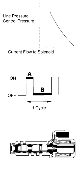
The throttle pressure that is applied to the primary regulator valve (which modulates the line pressure) causes solenoid valve SLT, under electronic control, to precisely modulate and generate the line pressure according to the extent that the accelerator pedal is depressed or the output of engine power.
This controls the line pressure and provides smooth shifting characteristics.
Upon receiving a signal of the throttle valve opening angle, the ECM controls the line pressure by sending a predetermined duty ratio* signal to the solenoid valve, modulating the line pressure and generating throttle pressure.
Tech Tips
*: The duty ratio is the ratio of the current ON time (A) to the total of the current ON and OFF time (A + B).
Duty Ratio (%) = A / (A + B) x 100
| DTC Code | DTC Detection Condition | Trouble Area |
|---|---|---|
| P2714 | The ECM detects a malfunction of shift solenoid valve SLT (ON side) according to difference in revolutions of the turbine (input) and output shaft (2 trip detection logic). |
|
MONITOR DESCRIPTION
In any forward position, when the difference between the revolutions of the turbine and output shaft exceeds the specified value (varies with output speed) determined by the ECM, the ECM illuminates the MIL and stores the DTC. When shift solenoid valve SLT remains on, the oil pressure goes down and the clutch engagement force decreases.
INSPECTION PROCEDURE
-
ACTIVE TEST
Tech Tips
Using the intelligent tester to perform Active Tests allows relays, VSVs, actuators and other items to be operated without removing any parts. This non-intrusive functional inspection can be very useful because intermittent operation may be discovered before parts or wiring is disturbed. Performing Active Tests early in troubleshooting is one way to save diagnostic time. Data List information can be displayed while performing Active Tests.
-
Warm up the engine.
-
Turn the ignition switch off.
-
Connect the intelligent tester to the DLC3.
-
Turn the ignition switch to ON.
-
Turn the intelligent tester on.
-
Enter the following menus: Powertrain / Engine and ECT / Active Test.
-
According to the display on the tester, perform the Active Test.
Engine and ECT Tester Display Test Part Control Range Diagnostic Note Activate the Solenoid (SLT)* Operate shift solenoid valve SLT and raise line pressure ON or OFF
Tech Tips
OFF: Line pressure up (when Active Test "Activate the Solenoid (SLT)" is performed, ECM commands SLT solenoid to turn OFF)
ON: No action (normal operation)
[Vehicle Condition]
-
The vehicle is stopped.
-
The engine is idling.
Tech Tips
*: "Activate the Solenoid (SLT)" in the Active Test is performed to check the line pressure changes by connecting SST to the automatic transaxle, which is used in the Hydraulic Test Click here as well. Note that the pressure values in the Active Test and Hydraulic Test are different.
-
-
PROCEDURE
-
CHECK OTHER DTCS OUTPUT (IN ADDITION TO DTC P2714)
-
Connect the intelligent tester to the DLC3.
-
Turn the ignition switch to ON.
-
Turn the intelligent tester on.
-
Enter the following menus: Powertrain / Engine and ECT / DTC.
-
Read the DTCs using the tester.
Result Result Proceed to Only P2714 is output A P2714 and other DTCs are output B Tech Tips
If any other codes besides P2714 are output, perform troubleshooting for those DTCs first.
B 
GO TO DTC CHART Click here
A 
-
-
INSPECT SHIFT SOLENOID VALVE SLT
-
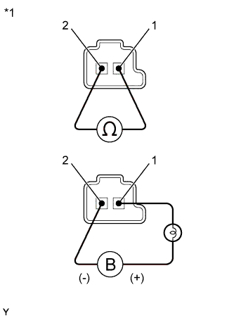
Text in Illustration *1 Component without harness connected
(Shift Solenoid Valve SLT)
Remove shift solenoid valve SLT.
-
Measure the resistance according to the value(s) in the table below.
Standard Resistance Tester Connection Condition Specified Condition 1 - 2 20°C (68°F) 5.0 to 5.6 Ω -
Apply 12 V battery voltage to the shift solenoid valve and check that the valve moves and makes an operating noise.
OK Measurement Condition Specified Condition
-
Battery positive (+) with a 21 W bulb → Terminal 1
-
Battery negative (-) → Terminal 2
Valve moves and makes an operating noise -
NG
REPLACE SHIFT SOLENOID VALVE SLT Click here
OK
-
-
INSPECT TRANSMISSION VALVE BODY ASSEMBLY
-
Check the transmission valve body assembly Click here.
OK There are no foreign objects on any valve.
NG
REPAIR OR REPLACE TRANSMISSION VALVE BODY ASSEMBLY Click here
OK
-
-
INSPECT TORQUE CONVERTER CLUTCH ASSEMBLY
-
Check the torque converter clutch assembly Click here.
OK The torque converter clutch operates normally.
NG
REPLACE TORQUE CONVERTER CLUTCH ASSEMBLY Click here
OK 
REPAIR OR REPLACE AUTOMATIC TRANSAXLE ASSEMBLY Click here
-