AUTOMATIC TRANSAXLE SYSTEM (for 1AZ-FE), Diagnostic DTC:P2716

| DTC Code | DTC Name |
|---|---|
| P2716 | Pressure Control Solenoid "D" Electrical (Shift Solenoid Valve SLT) |
DESCRIPTION
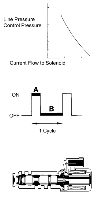
The throttle pressure that is applied to the primary regulator valve (which modulates the line pressure) causes solenoid valve SLT, under electronic control, to precisely modulate and generate the line pressure according to the extent that the accelerator pedal is depressed or the output of engine power.
This controls the line pressure and provides smooth shifting characteristics.
Upon receiving a signal of the throttle valve opening angle, the ECM controls the line pressure by sending a predetermined duty ratio* signal to the solenoid valve, modulating the line pressure and generating throttle pressure.
Tech Tips
*: The duty ratio is the ratio of the current ON time (A) to the total of the current ON and OFF time (A + B).
Duty Ratio (%) = A / (A + B) x 100
| DTC Code | DTC Detection Condition | Trouble Area |
|---|---|---|
| P2716 | The duty cycle to shift solenoid valve SLT is 100% (1 trip detection logic). |
|
MONITOR DESCRIPTION
When an open or short in the shift solenoid valve SLT circuit is detected, the ECM interprets this as a fault. Then the ECM illuminates the MIL and stores the DTC.
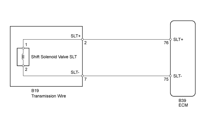
WIRING DIAGRAM
INSPECTION PROCEDURE
PROCEDURE
-
INSPECT TRANSMISSION WIRE (SHIFT SOLENOID VALVE SLT)
-
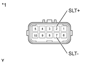
Text in Illustration *1 Component without harness connected
(Transmission Wire)
Disconnect the B19 transmission wire connector.
-
Measure the resistance according to the value(s) in the table below.
Standard Resistance Tester Connection Condition Specified Condition 2 (SLT+) - 7 (SLT-) 20°C (68°F) 5.0 to 5.6 Ω 2 (SLT+) - Body ground Always 10 kΩ or higher 7 (SLT-) - Body ground Always 10 kΩ or higher
NG 
INSPECT SHIFT SOLENOID VALVE SLT Click here
OK 
-
-
CHECK HARNESS AND CONNECTOR (TRANSMISSION WIRE - ECM)
-
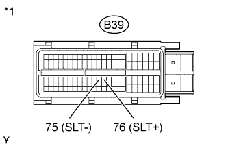
Text in Illustration *1 Front view of wire harness connector
(to ECM)
Disconnect the B39 ECM connector.
-
Measure the resistance according to the value(s) in the table below.
Standard Resistance Tester Connection Condition Specified Condition B39-76 (SLT+) - B39-75 (SLT-) 20°C (68°F) 5.0 to 5.6 Ω B39-76 (SLT+) - Body ground Always 10 kΩ or higher B39-75 (SLT-) - Body ground Always 10 kΩ or higher
NG 
REPAIR OR REPLACE HARNESS OR CONNECTOR
OK 
REPLACE ECM Click here
-
-
INSPECT SHIFT SOLENOID VALVE SLT
-
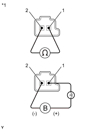
Text in Illustration *1 Component without harness connected
(Shift Solenoid Valve SLT)
Remove shift solenoid valve SLT.
-
Measure the resistance according to the value(s) in the table below.
Standard Resistance Tester Connection Condition Specified Condition 1 - 2 20°C (68°F) 5.0 to 5.6 Ω -
Apply 12 V battery voltage to the shift solenoid valve and check that the valve moves and makes an operating noise.
OK Measurement Condition Specified Condition
-
Battery positive (+) with a 21 W bulb → Terminal 1
-
Battery negative (-) → Terminal 2
Valve moves and makes an operating noise -
NG
REPLACE SHIFT SOLENOID VALVE SLT Click here
OK
REPAIR OR REPLACE TRANSMISSION WIRE Click here
-