AUTOMATIC TRANSAXLE SYSTEM (for 1AZ-FE) TERMINALS OF ECM

-
CHECK ECM
Tech Tips
Each ECM terminal standard voltage is shown in the table below.
In the table, first follow the information under "Condition". Look under "Terminal No. (Symbol)" for the terminals to be inspected. The standard voltage between the terminals is shown under "Specified Condition".
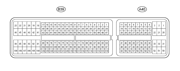
Use the illustration above as a reference for the ECM terminals.
Terminal No. (Symbol) Wiring Color Terminal Description Condition Specified Condition B39-52 (NSW) - B39-104 (E1) G - BR PNP switch signal
-
Engine switch on (IG)
-
Shift lever in P or N
Below 1 V B39-52 (NSW) - B39-104 (E1) G - BR PNP switch signal
-
Engine switch on (IG)
-
Shift lever not in P or N
11 to 14 V B39-73 (P) - B39-104 (E1) SB - BR P shift position switch signal
-
Engine switch on (IG)
-
Shift lever in P
11 to 14 V B39-73 (P) - B39-104 (E1) SB - BR P shift position switch signal
-
Engine switch on (IG)
-
Shift lever not in P
Below 1 V B39-53 (R) - B39-104 (E1) R - BR R shift position switch signal
-
Engine switch on (IG)
-
Shift lever in R
11 to 14 V B39-53 (R) - B39-104 (E1) R - BR R shift position switch signal
-
Engine switch on (IG)
-
Shift lever not in R
Below 1 V B39-54 (N) - B39-104 (E1) LG - BR N shift position switch signal
-
Engine switch on (IG)
-
Shift lever in N
11 to 14 V B39-54 (N) - B39-104 (E1) LG - BR N shift position switch signal
-
Engine switch on (IG)
-
Shift lever not in N
Below 1 V B39-56 (D) - B39-104 (E1) W - BR D shift position switch signal
-
Engine switch on (IG)
-
Shift lever in D
11 to 14 V B39-56 (D) - B39-104 (E1) W - BR D shift position switch signal
-
Engine switch on (IG)
-
Shift lever not in D
Below 1 V B39-74 (S) - B39-104 (E1) GR - BR S shift position switch signal
-
Engine switch on (IG)
-
Shift lever in S
11 to 14 V B39-74 (S) - B39-104 (E1) GR - BR S shift position switch signal
-
Engine switch on (IG)
-
Shift lever not in S
Below 1 V A40-16 (SFTU) - B39-104 (E1) W - BR Up-shift position switch signal
-
Engine switch on (IG)
-
Shift lever in S
11 to 14 V A40-16 (SFTU) - B39-104 (E1) W - BR Up-shift position switch signal
-
Engine switch on (IG)
-
Shift lever in "+" (up-shift)
Below 1 V A40-51 (SFTD) - B39-104 (E1) R - BR Down-shift position switch signal
-
Engine switch on (IG)
-
Shift lever in S
11 to 14 V A40-51 (SFTD) - B39-104 (E1) R - BR Down-shift position switch signal
-
Engine switch on (IG)
-
Shift lever in "-" (down-shift)
Below 1 V B39-57 (SL1+) - B39-77 (SL1-) P - R SL1 solenoid signal Engine idling Pulse generation
(see waveform 1)
B39-57 (SL1+) - B39-77 (SL1-) P - R SL1 solenoid signal Engine switch on (IG) 11 to 14 V B39-57 (SL1+) - B39-77 (SL1-) P - R SL1 solenoid signal In 1st gear 11 to 14 V B39-57 (SL1+) - B39-77 (SL1-) P - R SL1 solenoid signal Not in 1st gear Below 1 V B39-58 (SL2+) - B39-59 (SL2-) G - GR SL2 solenoid signal Engine idling Pulse generation
(see waveform 2)
B39-58 (SL2+) - B39-59 (SL2-) G - GR SL2 solenoid signal Engine switch on (IG) Below 1 V B39-58 (SL2+) - B39-59 (SL2-) G - GR SL2 solenoid signal In 1st or 2nd gear 11 to 14 V B39-58 (SL2+) - B39-59 (SL2-) G - GR SL2 solenoid signal In 3rd or 4th gear Below 1 V B39-79 (DSL) - B39-45 (E01) W - BR DSL solenoid signal Vehicle speed 65 km/h (40 mph), lock-up ON to OFF Pulse generation
(see waveform 3)
B39-76 (SLT+) - B39-75 (SLT-) LG - V SLT solenoid signal Engine idling Pulse generation
(see waveform 4)
B39-78 (S4) - B39-45 (E01) SB - BR S4 solenoid signal Engine switch on (IG) Below 1 V B39-78 (S4) - B39-45 (E01) SB - BR S4 solenoid signal In 4th gear 11 to 14 V B39-78 (S4) - B39-45 (E01) SB - BR S4 solenoid signal Not in 4th gear Below 1 V B39-72 (THO1) - B39-95 (ETHO) Y- R ATF temperature sensor signal ATF temperature 115°C (239°F) or higher Below 1.5 V B39-125 (NT+) - B39-124 (NT-) R - W Speed sensor (NT) signal Vehicle speed 20 km/h (12 mph) Pulse generation
(see waveform 5)
B39-101 (NC+) - B39-102 (NC-) G - P Speed sensor (NC) signal
-
Vehicle speed 30 km/h (19 mph) (3rd gear)
-
Engine speed 1400 rpm
Pulse generation
(see waveform 6)
-
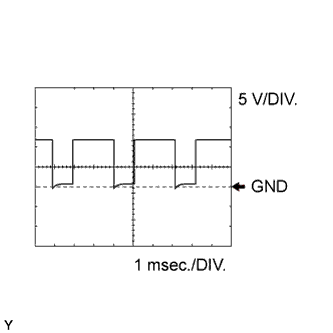
Using an oscilloscope, check waveform 1.
Reference Terminal No. (Symbol) Tool Setting Condition B39-57 (SL1+) - B39-77 (SL1-) 5 V/DIV., 1 msec./DIV. Engine idling -
Using an oscilloscope, check waveform 2.
Reference Terminal No. (Symbol) Tool Setting Condition B39-58 (SL2+) - B39-59 (SL2-) 5 V/DIV., 1 msec./DIV. Engine idling -
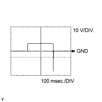
Using an oscilloscope, check waveform 3.
Reference Terminal No. (Symbol) Tool Setting Condition B39-79 (DSL) - B39-45 (E01) 10 V/DIV., 100 msec./DIV. Vehicle speed 65 km/h (40 mph), lock-up ON to OFF -
Using an oscilloscope, check waveform 4.
Reference Terminal No. (Symbol) Tool Setting Condition B39-76 (SLT+) - B39-75 (SLT-) 5 V/DIV., 1 msec./DIV. Engine idling -
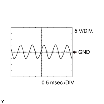
Using an oscilloscope, check waveform 5.
Reference Terminal No. (Symbol) Tool Setting Condition B39-125 (NT+) - B39-124 (NT-) 5 V/DIV., 0.5 msec./DIV. Vehicle speed 20 km/h (12 mph) -
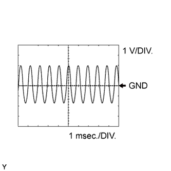
Using an oscilloscope, check waveform 6.
Reference Terminal No. (Symbol) Tool Setting Condition B39-101 (NC+) - B39-102 (NC-) 1 V/DIV., 1 msec./DIV.
-
Vehicle speed 30 km/h (19 mph) (3rd gear)
-
Engine speed 1400 rpm
-
-