RADIATOR INSTALLATION

-
INSTALL RADIATOR DRAIN COCK PLUG
-
Install a new O-ring to the drain cock plug.
-
Install the drain cock plug.
-
-
INSTALL FAN SHROUD WITH COOLING FAN
-
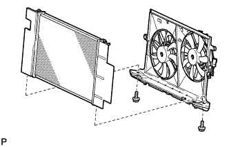
Install the fan shroud with cooling fan to the radiator with the 2 bolts.
- Torque:
- 7.0 N*m { 71 kgf*cm, 62 in.*lbf }
-
-
INSTALL CONDENSER ASSEMBLY WITH RECEIVER
-
Install the 4 cooler condenser cushions to the condenser assembly with receiver.
-
Install the condenser assembly with receiver.
-
-
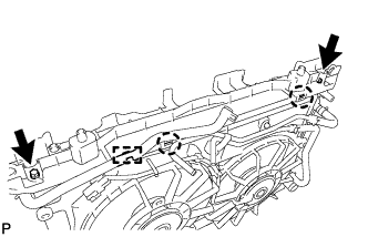
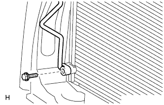
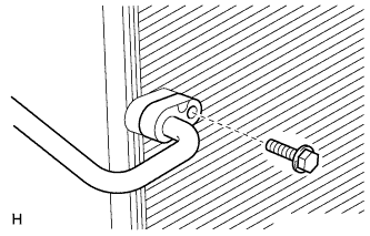
INSTALL OIL COOLER TUBE ASSEMBLY
-
Install the oil cooler tube with the 2 bolts.
- Torque:
- 5.5 N*m { 56 kgf*cm, 49 in.*lbf }
-
Connect the oil cooler tube and attach the clamp.
-
-
INSTALL NO. 3 WATER BY-PASS HOSE
-
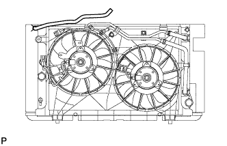
Install the No. 3 water by-pass hose.
-
-
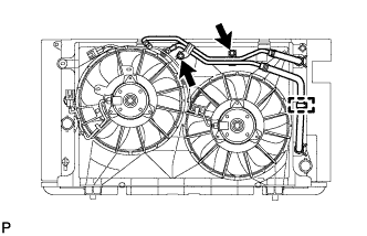
INSTALL NO. 2 FAN SHROUD
-
Attach the No. 2 fan shroud with the 2 claws.
-
Install the 2 bolts.
- Torque:
- 7.0 N*m { 71 kgf*cm, 62 in.*lbf }
-
Connect the No. 3 water by-pass hose to the No. 2 fan shroud.
-
-
INSTALL RADIATOR ASSEMBLY
-
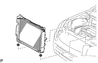
Install the 2 lower radiator support cushions to the fan shroud.
-
Install the radiator with cooler condenser and fan shroud to the lower radiator support.
-
-
INSTALL RADIATOR SUPPORT CUSHION
-
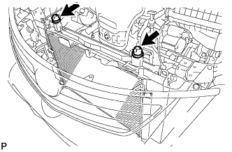
Install the 2 radiator support cushions.
-
-
INSTALL UPPER RADIATOR SUPPORT
-
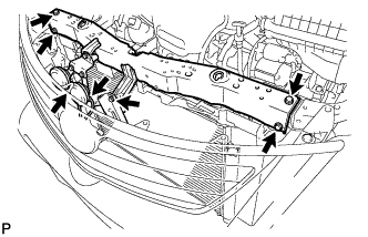
Install the upper radiator support with the 5 bolts.
- Torque:
- 13 N*m { 127 kgf*cm, 9 ft.*lbf }
-
Connect the 2 horn connectors.
-
-
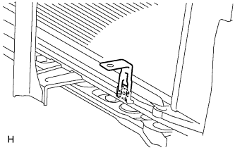
INSTALL AMBIENT TEMPERATURE SENSOR
-
Attach the claw to install the cooler bracket.
-
Attach the clamp to install the sensor.
-
Connect the connector.
-
-
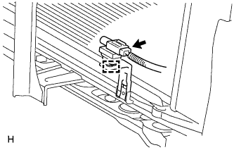
CONNECT SUCTION PIPE SUB-ASSEMBLY
-
Remove the attached vinyl tape from the pipe and the connecting part of the cooler condenser assembly.
-
Sufficiently apply compressor oil to a new O-ring and the fitting surface of the pipe joint.
Compressor oil ND-OIL 8 or equivalent -
Install the O-ring to the suction pipe sub-assembly.
-
Install the suction pipe sub-assembly to the cooler condenser assembly with the bolt.
- Torque:
- 5.4 N*m { 55 kgf*cm, 48 in.*lbf }
-
-
CONNECT DISCHARGE HOSE SUB-ASSEMBLY
-
Remove the attached vinyl tape from the hose and the connecting part of the cooler condenser assembly.
-
Sufficiently apply compressor oil to a new O-ring and the fitting surface of the hose joint.
Compressor oil ND-OIL 8 or equivalent -
Install the O-ring to the discharge hose sub-assembly.
-
Install the discharge hose sub-assembly to the cooler condenser assembly with the bolt.
- Torque:
- 5.4 N*m { 55 kgf*cm, 48 in.*lbf }
-
-
INSTALL HOOD LOCK ASSEMBLY
-
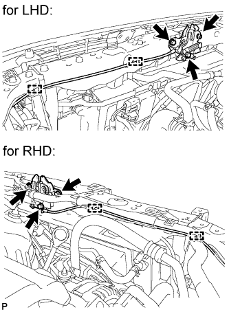
Connect the hood lock with the 3 bolts.
- Torque:
- 7.5 N*m { 77 kgf*cm, 66 in.*lbf }
-
Connect the 2 clamps.
-
-
INSTALL NO. 1 WATER HOSE CLAMP BRACKET
-
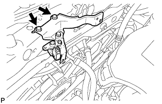
Install the No. 1 water hose clamp bracket with the 2 bolts.
- Torque:
- 5.0 N*m { 51 kgf*cm, 44 in.*lbf }
-
-
CONNECT COOLING FAN MOTOR HARNESS
-
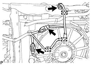
Connect the 3 clamps and variable resistor connector.
-
Connect the 2 fan motor connectors.
-
-
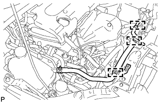
CONNECT OIL COOLER HOSE
-
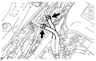
Connect the 2 oil cooler hoses.
-
-
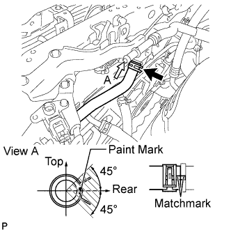
CONNECT NO. 1 WATER BY-PASS HOSE
-
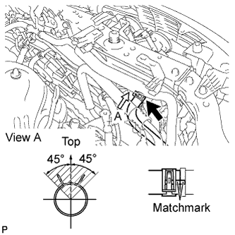
Connect the No. 1 water by-pass hose.
Tech Tips
The direction of the hose clamp is indicated in the illustration.
-
-
INSTALL NO. 2 WATER BY-PASS HOSE
-
Install the No. 2 water by-pass hose with the 3 clamps.
-
-
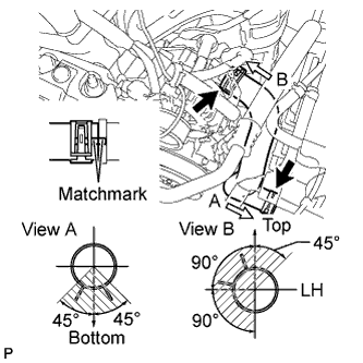
CONNECT NO. 3 WATER BY-PASS HOSE
-
Connect the No. 3 water by-pass hose to the No. 2 water by-pass hose.
Tech Tips
The direction of the hose clamp is indicated in the illustration.
-
-
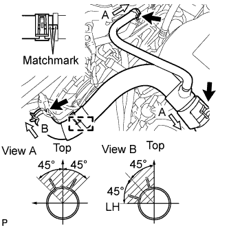
INSTALL NO. 2 RADIATOR HOSE
-
Install the No. 2 radiator hose.
Tech Tips
The direction of the hose clamp is indicated in the illustration.
-
-
INSTALL NO. 1 RADIATOR HOSE
-
Install the No. 1 radiator hose.
-
Connect the No. 1 radiator hose to the No. 2 water by-pass hose.
-
Connect the No. 1 radiator hose clamp.
Tech Tips
The direction of the hose clamp is indicated in the illustration.
-
-
INSTALL BATTERY
-
INSTALL BATTERY CLAMP SUB-ASSEMBLY
-
Attach the hook of the battery clamp to the battery carrier.
-
Partially tighten the nut and temporarily install the bolt so that the clamp position can be adjusted.
-
Adjust the battery clamp position.
-
Tighten the nut and bolt.
- Torque:
- for bolt
- 17 N*m { 168 kgf*cm, 12 ft.*lbf }
- for nut
- 3.5 N*m { 36 kgf*cm, 31 in.*lbf }
-
-
ADD ENGINE COOLANT
-
Add TOYOTA Super Long Life Coolant (SLLC) to the radiator reservoir filler opening.
-
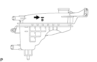
Continue adding TOYOTA SLLC until it is filled to the B line.
Standard capacity 5.7 liters (6.0 US qts, 5.0 Imp. qts) Note
Do not substitute plain water for engine coolant.
Tech Tips
TOYOTA vehicles are filled with TOYOTA SLLC at the factory. In order to avoid damage to the engine cooling system and other technical problems, only use TOYOTA SLLC or similar high quality ethylene glycol based non-silicate, non-amine, non-nitrite, non-borate coolant with long-life hybrid organic acid technology (coolant with long-life hybrid organic acid technology is a combination of low phosphates and organic acids).
-
Press the No. 1 and No. 2 radiator hoses several times by hand, and then check the level of the coolant. If the coolant level drops below the B line, add TOYOTA SLLC to the B line.
-
Install the radiator cap.
-
Start the engine and warm it up until the cooling fan operates. While the cooling fan operates, circulate the coolant for several minutes.
-
Set the air conditioning as follows while warming up the engine.
Item Specified Condition Automatic Air Conditioning System Temperature: Toward MAX (HOT)
Air conditioning switch: off
-
Maintain an engine speed of 2000 to 2500 rpm and warm up the engine until the cooling fan operates.
Note
-
Make sure that the radiator reservoir still has some coolant in it.
-
Pay attention to the needle of the water temperature meter. Make sure that the needle does not show an abnormally high temperature.
-
If there is not enough coolant, the engine may burn out or overheat.
-
Immediately after starting the engine, if the radiator reservoir does not have any coolant, perform the following: 1) stop the engine, 2) wait until the coolant has cooled down, and 3) add coolant until the coolant is filled to the B line.
-
Run the engine at 2000 rpm until the coolant level has stabilized.
-
-
-
Press the No. 1 and No. 2 radiator hoses several times by hand to bleed air.
CAUTION:
When pressing the radiator hoses:
-
Wear protective gloves.
-
Be careful as the radiator hoses are hot.
-
Keep your hands away from the radiator fan.
-
-
Stop the engine and wait until the coolant cools down to ambient temperature.
-
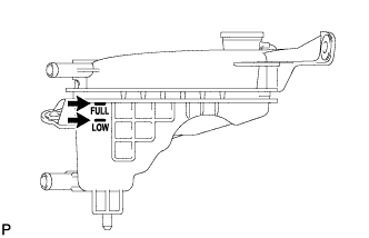
Check that the coolant level is between the FULL and LOW lines.
If the coolant level is below the LOW line, repeat all of the procedures above.
If the coolant level is above the FULL line, drain coolant so that the coolant level is between the FULL and LOW lines.
-
-
INSPECT FOR COOLANT LEAK
-
Remove the radiator cap.
CAUTION:
To avoid the danger of being burned, do not remove the radiator cap while the engine and radiator are still hot. Thermal expansion will cause hot engine coolant and steam to blow out from the radiator reservoir.
-
Fill the radiator reservoir with coolant, and then attach a radiator cap tester.
-
Warm up the engine.
-
Pump the radiator cap tester to 118 kPa (1.2 kgf/cm2, 17 psi), and then check that the pressure does not drop.
If the pressure drops, check the hoses, radiator and water pump for leakage.
If there are no signs of external coolant leaks, check the heater core, cylinder block and head.
-
Reinstall the radiator cap.
-
-
CHARGE REFRIGERANT
- SST
- 09985-20010 ( 09985-02130, 09985-02150, 09985-02090, 09985-02110, 09985-02010, 09985-02050, 09985-02060, 09985-02070 )
-
Perform vacuum purging using a vacuum pump.
-
Charge refrigerant HFC-134a (R134a).
Standard 440 +/-30 g (15.5 +/-1.1 oz) 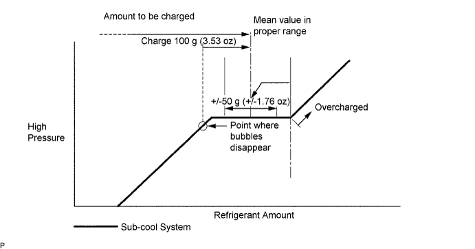
Note
-
Do not operate the cooler compressor before charging refrigerant as the cooler compressor will not work properly without any refrigerant, and will overheat.
-
Approximately 200 g (7.05 oz) of refrigerant may need to be charged after bubbles disappear. The refrigerant amount should be checked by measuring its quantity, and not with the sight glass.
-
-
WARM UP ENGINE
-
Warm up the engine at less than 1850 rpm for 2 minutes or more after charging the refrigerant.
Note
Be sure to warm up the compressor when turning the A/C switch on after removing and installing the cooler refrigerant lines (including the compressor) to prevent damage to the compressor.
-
-
CHECK FOR REFRIGERANT GAS LEAK
-
After recharging the refrigerant gas, check for refrigerant gas leakage using a halogen leak detector.
-
Perform the operation observing the following instructions:
-
Stop the engine.
-
Secure good ventilation (the halogen leak detector may react to volatile gases other than refrigerant, such as evaporated gasoline or exhaust gas).
-
Repeat the test 2 or 3 times.
-
Make sure that some refrigerant remains in the refrigeration system.
Tech Tips
When the compressor is off: approximately 392 to 588 kPa (4.0 to 6.0 kgf/cm2, 57 to 85 psi).
-
-
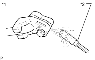
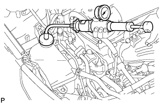
Text in Illustration *1 Check for Leakage *2 Halogen Leak Detector Using a halogen leak detector, check the refrigerant line for leakage.
-
If a gas leak is not detected from the drain hose, remove the blower motor control (blower resistor) from the cooling unit. Insert the halogen leak detector sensor into the unit and check for gas leakage.
-
Disconnect the pressure switch connector and wait for approximately 20 minutes. Bring the halogen leak detector close to the pressure switch and check for gas leakage.
-
-
INSTALL NO. 1 ENGINE UNDER COVER (for Rough Road Area Specification Vehicles)
-
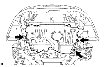
Install the under cover with the 3 bolts.
-
-
INSTALL NO. 1 ENGINE UNDER COVER
-
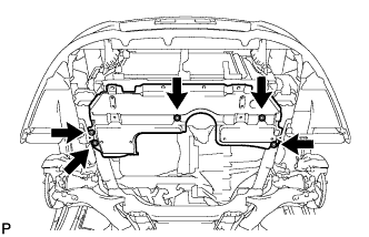
Install the under cover with the 5 clips.
-
-
INSTALL FRONT LOWER BUMPER ABSORBER
-
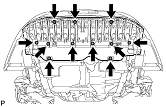
Install the front lower bumper absorber with the 8 bolts and 3 screws.
-
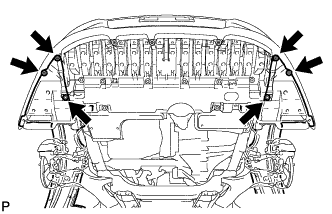
Install the 4 screws and 2 bolts.
-
-
INSTALL RADIATOR SUPPORT OPENING COVER
-
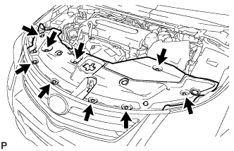
Install the radiator support opening cover with the 9 clips.
-