INTAKE MANIFOLD REMOVAL

-
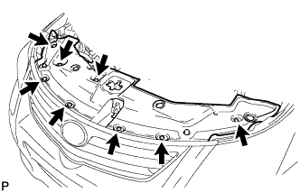
REMOVE ENGINE ROOM SIDE COVER
-
Remove the clip and engine room side cover.
-
-
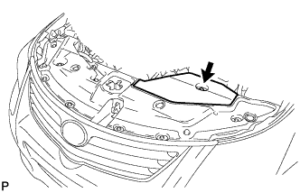
REMOVE RADIATOR SUPPORT OPENING COVER
-
Remove the 8 clips and radiator support opening cover.
-
-
DRAIN ENGINE COOLANT
-
Loosen the radiator drain cock plug.
Tech Tips
Collect the coolant in a container and dispose of it according to the regulations in your area.
-
Remove the reserve tank cap.
CAUTION:
Do not remove the reserve tank cap while the engine and radiator are still hot.
Pressurized, hot engine coolant and steam may be released and cause serious burns.
-
Loosen the cylinder block drain cock plug.
Tech Tips
The plug is on the exhaust manifold side.
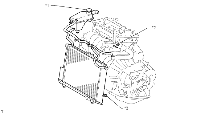
Text in Illustration *1 Reserve Tank Cap *2 Cylinder Block Drain Cock Plug *3 Radiator Drain Cock Plug -
-
-
DISCONNECT CABLE FROM NEGATIVE BATTERY TERMINAL
Note
When disconnecting the cable, some systems need to be initialized after the cable is reconnected Click here.
-
REMOVE NO. 2 CYLINDER HEAD COVER
-
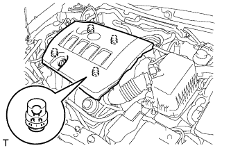
Hold the rear of the cover and raise it to detach the 2 clips on the rear of the cover. Continue to raise the cover to detach the 2 clips on the front of the cover and remove the cover.
Note
Attempting to detach both front and rear clips at the same time may cause the cover to break.
-
-
REMOVE REAR ENGINE UNDER COVER RH
-
Remove the 5 clips and under cover RH.
-
-
REMOVE V-RIBBED BELT
-

Loosen bolts A and B.
-
Loosen bolt C and remove the V-ribbed belt.
Note
Do not loosen bolt D.
-
-
REMOVE GENERATOR ASSEMBLY
-
Remove the terminal cap.
-
Remove the nut and disconnect the wire harness from terminal B.
-
Disconnect the connector and wire harness clamp.
-
Loosen the 3 bolts.
-
Remove the 2 bolts and adjusting bar.
-
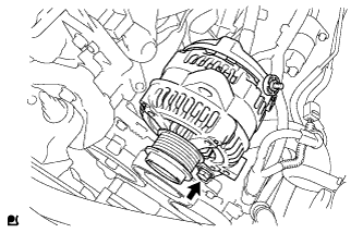
Remove the bolt and generator.
-

Remove the bolt and wire harness clamp bracket.
-
-
REMOVE AIR CLEANER CAP SUB-ASSEMBLY
-
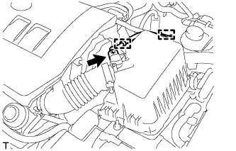
Disconnect the mass air flow meter connector.
-
Detach the wire harness from the 2 clamps.
-
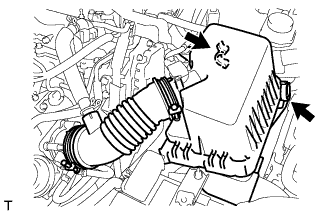
Disconnect the 2 clamps.
-
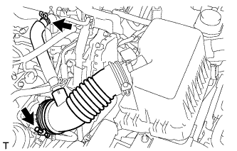
Disconnect the ventilation hose.
-
Loosen the band and remove the air cleaner cap.
-
-
REMOVE THROTTLE BODY ASSEMBLY
-
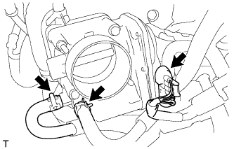
Disconnect the throttle body connector and 2 water hoses.
-
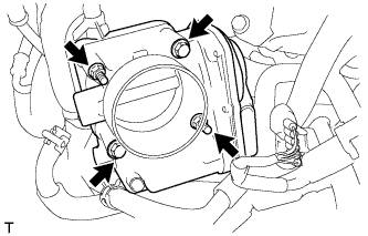
Remove the 2 bolts, 2 nuts and throttle body.
-
Remove the gasket.
-
-
REMOVE VACUUM SENSOR ASSEMBLY
-
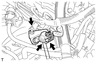
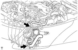
Disconnect the vacuum sensor connector.
-
Remove the bolt and vacuum sensor.
-
Disconnect the air hose from the vacuum sensor.
-
-
REMOVE NO. 1 VACUUM SWITCHING VALVE ASSEMBLY
-
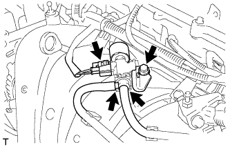
Disconnect the connector and 2 vacuum hoses.
-
Remove the bolt and vacuum switching valve.
-
-
REMOVE INTAKE MANIFOLD
-
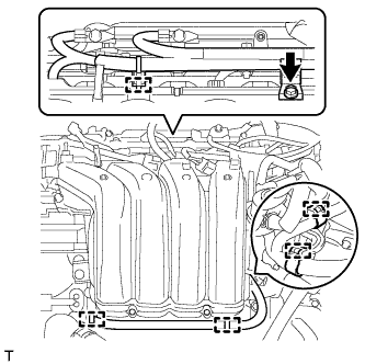
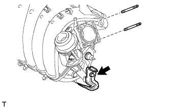
Remove the bolt and wire harness clamp bracket.
-
Detach the 5 clamps and wire harness from the intake manifold.
-
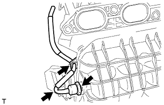
Disconnect the fuel vapor feed hose and ventilation hose.
-
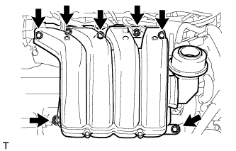
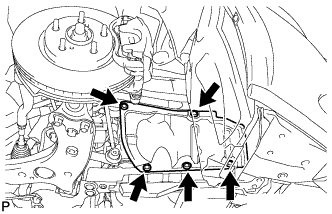
Remove the 5 bolts, 2 nuts, intake manifold stay and intake manifold.
-
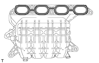
Remove the gasket from the intake manifold.
-
Remove the bolt and wire harness clamp bracket from the intake manifold.
-
Using an E6 "TORX" socket wrench, remove the 2 stud bolts from the intake manifold.
-
-
REMOVE NO. 1 GAS FILTER
-
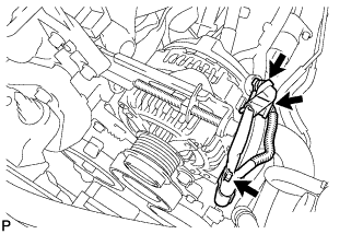
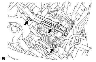
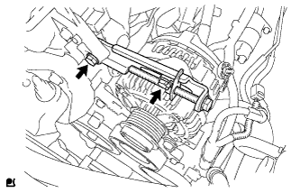
Disconnect the air hose from the gas filter and intake manifold.
-
Using a 24 mm deep socket wrench, remove the gas filter from the intake manifold.
-
-
REMOVE ENGINE COVER JOINT
-
Remove the engine cover joint.
-