INTAKE MANIFOLD INSTALLATION

-
INSTALL NO. 1 INTAKE MANIFOLD INSULATOR
-
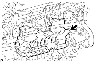
Install the No. 1 intake manifold insulator to the cylinder block.
-
-
INSTALL INTAKE MANIFOLD
-
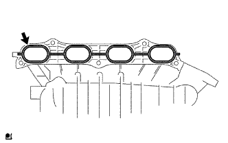
Install a new gasket to the intake manifold.
-
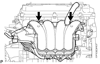
Install the intake manifold with the 2 stud bolts.
- Torque:
- 9.5 N*m { 97 kgf*cm, 84 in.*lbf }
-
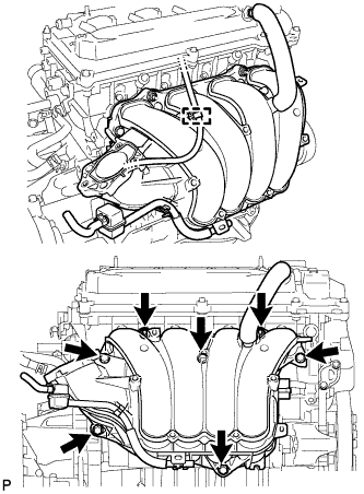
Install the 5 bolts and 2 nuts.
- Torque:
- 30 N*m { 306 kgf*cm, 22 ft.*lbf }
-
Connect the wire harness clamp.
-
Connect the connector tube hose to the brake booster.
-
-
CONNECT OUTLET HEATER WATER HOSE
-
Connect the outlet heater water hose.
-
-
CONNECT INLET HEATER WATER HOSE
-
Connect the inlet heater water hose.
-
-
INSTALL FUEL INJECTOR ASSEMBLY
-

Text in Illustration *1 O-Ring Apply a light coat of gasoline or spindle oil to new O-rings and install one onto each fuel injector.
-
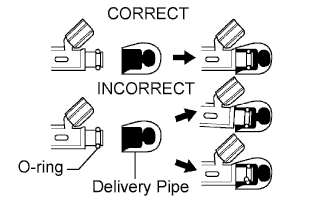
Apply a light coat of gasoline or spindle oil to the part of the fuel delivery pipe which comes into contact with the O-ring of the fuel injector.
-
Apply a light coat of gasoline or spindle oil to the O-ring again and install the fuel injectors onto the fuel delivery pipe.
Note
Make sure that the O-ring is not cracked or jammed when installing.
-
Check that the fuel injector rotates smoothly.
If the fuel injector does not rotate, replace the O-ring.
-
-
INSTALL FUEL DELIVERY PIPE SUB-ASSEMBLY
-
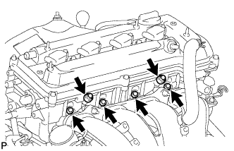
Install 4 new insulators to the cylinder head.
-
Install the 2 delivery pipe spacers to the cylinder head.
-
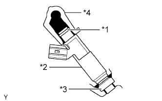
Text in Illustration *1 O-Ring *2 Fuel Injector *3 Insulator *4 Fuel Delivery Pipe Install the fuel delivery pipe together with the 4 fuel injectors, and then temporarily install the 2 bolts.
Note
Be careful not to drop the fuel injectors when installing the fuel delivery pipe.
-
Check that the fuel injector rotates smoothly.
If the fuel injector does not rotate, replace the O-ring.
-
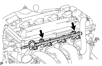
Tighten the 2 bolts.
- Torque:
- 20 N*m { 204 kgf*cm, 15 ft.*lbf }
-
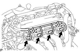
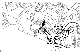
Connect the 4 fuel injector connectors.
-
Connect the 2 wire harness clamps.
-
-
CONNECT FUEL TUBE
-
Connect the fuel tube.
-
Push the fuel tube connector until it makes a "click" sound.
-
Install the fuel pipe clamp.
-
Install the fuel tube to the fuel hose clamp.
-
-
-
CONNECT NO. 2 VENTILATION HOSE
-
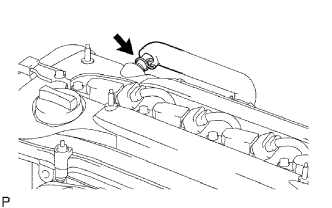
Connect the ventilation hose to the ventilation valve.
-
-
INSTALL THROTTLE BODY ASSEMBLY
-
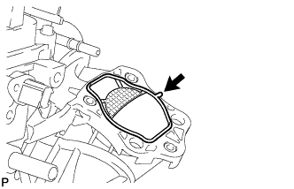
Install a new gasket to the intake manifold.
-
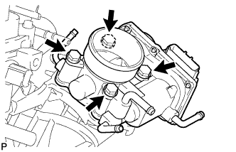
Install the throttle body with the 4 bolts.
- Torque:
- 30 N*m { 306 kgf*cm, 22 ft.*lbf }
-
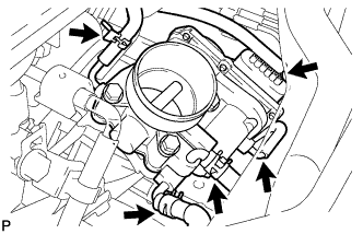
Connect the throttle position sensor and control motor connector.
-
Connect the throttle hose to the throttle body.
-
Connect the No. 2 water by-pass hose to the throttle body.
-
Connect the No. 1 water by-pass hose to the throttle body.
-
Connect the No. 2 fuel vapor feed hose to the throttle body.
-
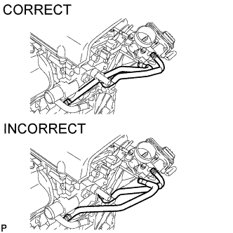
Make sure that the water by-pass hoses are installed as shown in the illustration.
-
-
INSTALL AIR CLEANER CAP AND HOSE
-
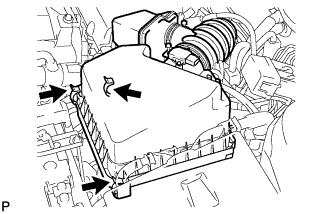
Insert the hinge part of the air cleaner cap and hose into the air cleaner case, and then fasten the 3 hook clamps.
-
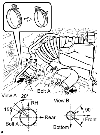
Align the matchmarks of the No. 1 air cleaner hose and throttle body. Then connect the No. 1 air cleaner hose to the throttle body and push apart the tabs of the No. 1 air cleaner hose clamp.
Note
Make sure that the hose clamp is at the correct angle.
-
Connect the No. 2 fuel vapor feed hose to the air cleaner hose.
-
Connect the No. 2 ventilation hose to the air cleaner hose.
-
Connect the purge VSV.
-
Connect the wire harness and mass air flow meter connector.
-
-
ADD ENGINE COOLANT
-
Add TOYOTA Super Long Life Coolant (SLLC) to the radiator reservoir filler opening.
-
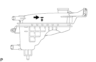
Continue adding TOYOTA SLLC until it is filled to the B line.
Standard capacity 5.7 liters (6.0 US qts, 5.0 Imp. qts) Note
Do not substitute plain water for engine coolant.
Tech Tips
TOYOTA vehicles are filled with TOYOTA SLLC at the factory. In order to avoid damage to the engine cooling system and other technical problems, only use TOYOTA SLLC or similar high quality ethylene glycol based non-silicate, non-amine, non-nitrite, non-borate coolant with long-life hybrid organic acid technology (coolant with long-life hybrid organic acid technology is a combination of low phosphates and organic acids).
-
Press the No. 1 and No. 2 radiator hoses several times by hand, and then check the level of the coolant. If the coolant level drops below the B line, add TOYOTA SLLC to the B line.
-
Install the radiator cap.
-
Start the engine and warm it up until the cooling fan operates. While the cooling fan operates, circulate the coolant for several minutes.
-
Set the air conditioning as follows while warming up the engine.
Item Specified Condition Automatic Air Conditioning System Temperature: Toward MAX (HOT)
Air conditioning switch: off
-
Maintain an engine speed of 2000 to 2500 rpm and warm up the engine until the cooling fan operates.
Note
-
Make sure that the radiator reservoir still has some coolant in it.
-
Pay attention to the needle of the water temperature meter. Make sure that the needle does not show an abnormally high temperature.
-
If there is not enough coolant, the engine may burn out or overheat.
-
Immediately after starting the engine, if the radiator reservoir does not have any coolant, perform the following: 1) stop the engine, 2) wait until the coolant has cooled down, and 3) add coolant until the coolant is filled to the B line.
-
Run the engine at 2000 rpm until the coolant level has stabilized.
-
-
-
Press the No. 1 and No. 2 radiator hoses several times by hand to bleed air.
CAUTION:
When pressing the radiator hoses:
-
Wear protective gloves.
-
Be careful as the radiator hoses are hot.
-
Keep your hands away from the radiator fan.
-
-
Stop the engine and wait until the coolant cools down to ambient temperature.
-
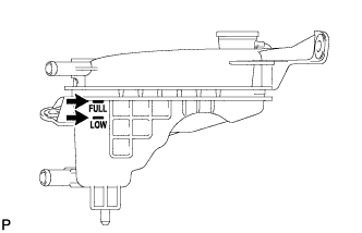
Check that the coolant level is between the FULL and LOW lines.
If the coolant level is below the LOW line, repeat all of the procedures above.
If the coolant level is above the FULL line, drain coolant so that the coolant level is between the FULL and LOW lines.
-
-
INSPECT FOR COOLANT LEAK
-
Remove the radiator cap.
CAUTION:
To avoid the danger of being burned, do not remove the radiator cap while the engine and radiator are still hot. Thermal expansion will cause hot engine coolant and steam to blow out from the radiator reservoir.
-
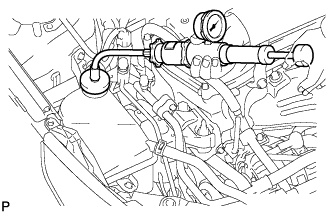
Fill the radiator reservoir with coolant, and then attach a radiator cap tester.
-
Warm up the engine.
-
Pump the radiator cap tester to 118 kPa (1.2 kgf/cm2, 17 psi), and then check that the pressure does not drop.
If the pressure drops, check the hoses, radiator and water pump for leakage.
If there are no signs of external coolant leaks, check the heater core, cylinder block and head.
-
Reinstall the radiator cap.
-
-
INSPECT FOR FUEL LEAK
-
Make sure that there are no fuel leaks after performing maintenance on the fuel system.
-
Connect the intelligent tester to the DLC3.
-
Turn the engine switch on (IG) and push the intelligent tester main switch on.
Note
Do not start the engine.
-
Select the Active Test mode on the intelligent tester.
Tech Tips
Refer to the intelligent tester operator's manual for further details.
-
Check that there are no leaks from the fuel system.
-
Turn the engine switch off.
-
Disconnect the intelligent tester from the DLC3.
-
-
-
INSTALL NO. 1 ENGINE COVER SUB-ASSEMBLY
-
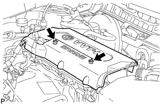
Install the cover with the 2 nuts.
- Torque:
- 9.0 N*m { 92 kgf*cm, 80 in.*lbf }
-
-
INSTALL RADIATOR SUPPORT OPENING COVER
-
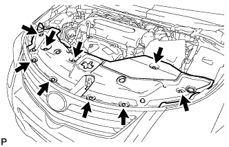
Install the radiator support opening cover with the 9 clips.
-
-
INSTALL OUTER COWL TOP PANEL SUB-ASSEMBLY
-
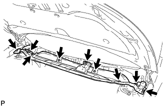
Install the outer cowl top panel with the 9 bolts.
- Torque:
- 8.8 N*m { 90 kgf*cm, 78 in.*lbf }
-
-
INSTALL FRONT WIPER MOTOR AND LINK ASSEMBLY
-
Install the front wiper motor and link Click here.
-