FUEL INJECTOR REMOVAL

-
DISCHARGE FUEL SYSTEM PRESSURE
-
Discharge fuel system pressure Click here.
-
-
REMOVE ENGINE ROOM SIDE COVER
-
Remove the clip and engine room side cover.
-
-
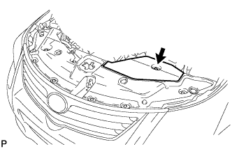
REMOVE RADIATOR SUPPORT OPENING COVER
-
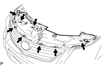
Remove the 8 clips and radiator support opening cover.
-
-
DISCONNECT CABLE FROM NEGATIVE BATTERY TERMINAL
Note
When disconnecting the cable, some systems need to be initialized after the cable is reconnected Click here.
-
REMOVE NO. 2 CYLINDER HEAD COVER
-
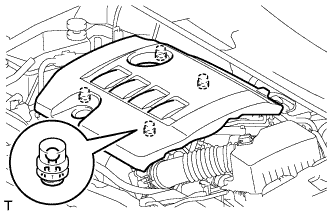
Hold the rear of the cover and raise it to detach the 2 clips on the rear of the cover. Continue to raise the cover to detach the 2 clips on the front of the cover and remove the cover.
Note
Attempting to detach both front and rear clips at the same time may cause the cover to break.
-
-
REMOVE AIR CLEANER CAP SUB-ASSEMBLY
-
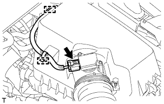
Disconnect the mass air flow meter connector.
-
Detach the wire harness from the 2 clamps.
-
Disconnect the 2 clamps.
-
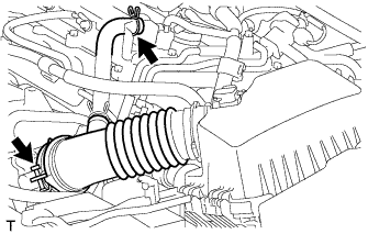
Disconnect the ventilation hose.
-
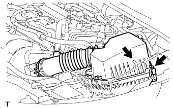
Loosen the band and remove the air cleaner cap.
-
-
REMOVE AIR CLEANER CASE SUB-ASSEMBLY
-
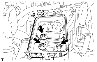
Detach the wire harness clamp from the air cleaner case.
-
Remove the 3 bolts and air cleaner case.
-
-
DISCONNECT ENGINE WIRE
-
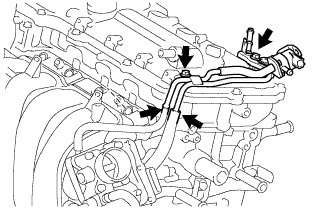
Remove the 2 bolts and disconnect the ground wires.
-
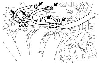
Disconnect the 4 fuel injector connectors.
-
Disconnect the 2 wire harness clamps.
-
Disconnect the 4 wire harness clamps.
-
Remove the 2 bolts and 2 wire harness brackets.
-
-
REMOVE AIR TUBE
-
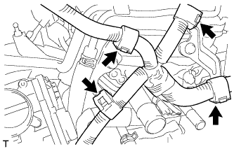
Disconnect the fuel vapor feed hose from the purge VSV.
-
Disconnect the union to connector tube hose.
-
Disconnect the No. 1 vacuum transmitting hose and No. 1 fuel vapor feed hose.
-
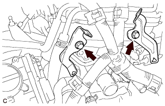
Remove the 2 bolts and air tube.
-
-
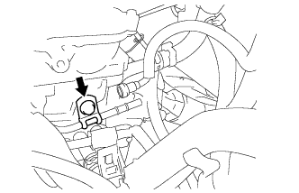
DISCONNECT FUEL TUBE SUB-ASSEMBLY
-
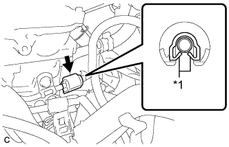
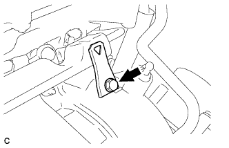
Text in Illustration *1 Claw Remove the No. 2 fuel pipe clamp.
-
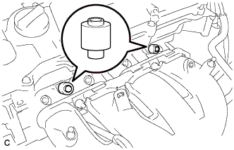
Wipe off any dirt on the fuel tube connector.
-
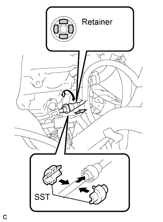
Hold the fuel tube connector and install SST.
- SST
- 09268-21010
-
Turn SST to align the retainer inside the fuel tube connector with the chamfered part of SST.
-
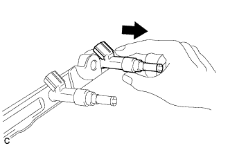
Insert SST into the fuel tube and hold it. Then push the fuel tube connector toward SST.
-
Mount the retainer of the fuel tube connector onto the chamfered part of SST.
-
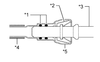
Text in Illustration *1 O-Ring *2 Retainer *3 Pipe *4 Nylon Tube *5 Fuel Tube Connector Slide SST and the fuel tube connector together towards the fuel tube until they make a "click" sound, and then disconnect the fuel tube.
-
Drain the fuel remaining inside the fuel tube.
-
Cover the fuel tube and fuel pipe with a plastic bag to protect the disconnected parts.
-
-
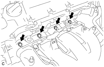
REMOVE FUEL DELIVERY PIPE SUB-ASSEMBLY
-
Remove the bolt and wire harness bracket.
-
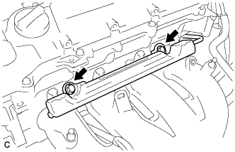
Remove the 2 bolts.
-
Remove the bolt and fuel delivery pipe.
-
Remove the 2 No. 1 delivery pipe spacers.
-
-
REMOVE FUEL INJECTOR ASSEMBLY
-
Pull the 4 fuel injector assemblies out of the fuel delivery pipe sub-assembly.
-
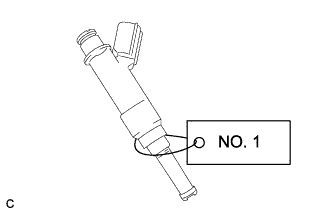
For reinstallation, attach a tag or label to the injector shaft.
Note
Prevent entry of foreign objects by covering the fuel injector with plastic bags.
-
Remove the 4 injector vibration insulators.
-