FUEL TANK INSTALLATION

-
REMOVE FUEL TANK ASSEMBLY
-
Set the fuel tank on a transmission jack.
-
Lift up the transmission jack.
Note
Be careful not to cut the wiring.
-
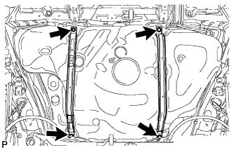
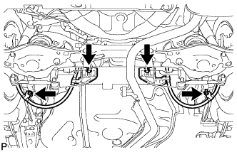
Install the fuel tank with the 2 fuel tank bands and 4 bolts.
- Torque:
- 39 N*m { 400 kgf*cm, 29 ft.*lbf }
-
-
CONNECT FUEL HOSE
-
Connect the No. 1 charcoal canister outlet hose.
-
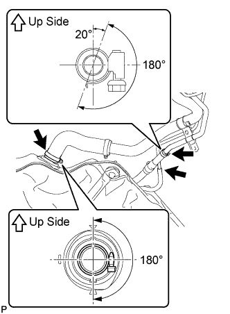
Connect the fuel tank vent hose as shown in the illustration.
Note
Be sure to tighten the hose clamp so that it is at the correct angle.
-
Connect the fuel tank to filler pipe hose as shown in the illustration.
Note
Be sure to tighten the hose clamp so that it is at the correct angle.
-
-
CONNECT FUEL TANK MAIN TUBE SUB-ASSEMBLY
-
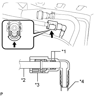
Text in Illustration *1 O-Ring *2 Fuel Pipe *3 Retainer *4 Nylon Tube Connect the fuel tank main tube.
Tech Tips
Push the parts together firmly until a "click" sound is heard.
Note
-
Before installing the tube connectors to the pipes, check if there is any damage or foreign matter in the connectors.
-
After the connection, check if the connectors and pipes are securely connected by trying to pull them apart.
-
-
-
CONNECT NO. 1 FUEL EVAPORATION TUBE SUB-ASSEMBLY
-
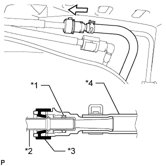
Text in Illustration *1 O-Ring *2 Fuel Pipe *3 Retainer *4 Nylon Tube Push the tube connector onto the fuel pipe and install the retainer.
Note
-
Check if there is any damage or foreign objects on the connection part of the fuel pipe.
-
After connecting, check if the fuel pipe and connector are securely connected by pulling on them.
-
-
-
CONNECT PARKING BRAKE CABLE
-
Connect the parking brake cable with the 2 bolts and 2 nuts.
- Torque:
- for nut
- 6.0 N*m { 61 kgf*cm, 53 in.*lbf }
- for bolt
- 35 N*m { 357 kgf*cm, 26 ft.*lbf }
-
-
INSTALL NO. 1 FUEL TANK PROTECTOR
-
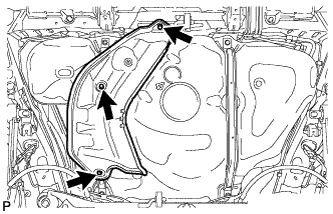
Install the No. 1 fuel tank protector with the 3 bolts.
- Torque:
- 5.5 N*m { 56 kgf*cm, 49 in.*lbf }
-
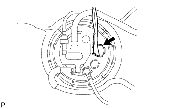
Connect the fuel pump connector.
-
-
INSTALL TAILPIPE ASSEMBLY
-
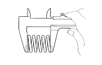
Using a vernier caliper, measure the free length of the compression springs.
Minimum free length 38.5 mm (1.52 in.) If the free length is less than the minimum, replace the compression spring.
-
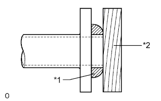
Text in Illustration *1 Gasket *2 Wooden Block Using a plastic-faced hammer and wooden block, tap in a new gasket until its surface is flush with the front exhaust pipe assembly.
Note
-
Be sure to install the gasket so that it faces the correct direction.
-
Do not reuse the gasket.
-
Do not damage the gasket.
-
When connecting the exhaust pipe, do not push in the gasket with the exhaust pipe.
-
-
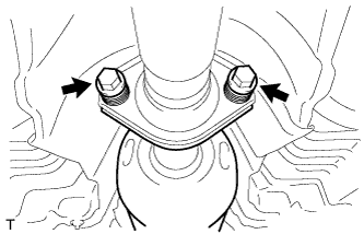
Install the 4 exhaust pipe supports, and then install the tailpipe assembly with the 2 bolts and 2 compression springs.
- Torque:
- 43 N*m { 439 kgf*cm, 32 ft.*lbf }
-
-
ADD FUEL
-
INSTALL FUEL TANK CAP ASSEMBLY
-
CONNECT CABLE TO NEGATIVE BATTERY TERMINAL
Note
When disconnecting the cable, some systems need to be initialized after the cable is reconnected Click here.
-
INSPECT FUEL LEAK
-
Make sure that there are no fuel leaks after performing maintenance on the fuel system.
-
Connect the intelligent tester to the DLC3.
-
Turn the ignition switch to ON, and push the intelligent tester main switch on.
Note
Do not start the engine.
-
Enter the following menus: Powertrain / Engine and ECT / Active Test / Control the Fuel Pump / Speed.
-
Check that there are no leaks from the fuel system.
-
Turn the ignition switch off.
-
Disconnect the intelligent tester from the DLC3.
-
-
-
INSTALL REAR FLOOR SERVICE HOLE COVER
-
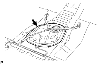
Install the rear floor service hole cover with new butyl tape.
-
-
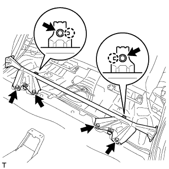
INSTALL NO. 1 QUARTER WHEEL HOUSE GUSSET SUB-ASSEMBLY
-
Align the 2 claws with the 2 gusset positioning holes and install the gusset with the 6 bolts.
- Torque:
- 44 N*m { 449 kgf*cm, 32 ft.*lbf }
-
-
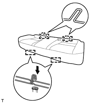
INSTALL REAR BENCH TYPE SEAT CUSHION ASSEMBLY (for Sedan)
-
Attach the 2 rear hooks of the seat cushion to the seatback.
-
Attach the 2 front hooks to install the seat cushion.
-
Confirm that the seat cushion is firmly installed.
Note
When installing the seat cushion, make sure the seat belt buckle is not under the seat cushion.
-
-
INSTALL REAR BENCH TYPE SEAT CUSHION ASSEMBLY (for Wagon)

-
Attach the 2 rear hooks of the seat cushion to the seatback.
-
Attach the 2 front hooks to install the seat cushion.
-
Confirm that the seat cushion is firmly installed.
Note
When installing the seat cushion, make sure the seat belt buckle is not under the seat cushion.
-