FUEL PUMP INSTALLATION

-
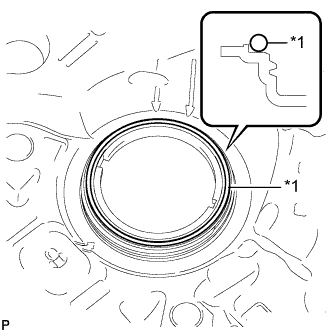
INSPECT FITTING OF FUEL PUMP GAUGE RETAINER
-
Inspect the fuel pump gauge retainer.
-
Install the fuel pump gauge retainer to the fuel tank by hand with the fuel suction with pump assembly disconnected.
-
If the fuel pump gauge retainer can be turned 180° or more by hand, reuse the retainer.
-
If the fuel pump gauge retainer cannot be turned 180° or more by hand, replace it with a new one.
Tech Tips
Check that there is no damage, dents, foreign matter, or other defects on the threads of the fuel tank.
-
-
-
-
INSTALL FUEL SUCTION WITH PUMP ASSEMBLY
-
Text in Illustration *1 New Gasket Install a new gasket onto the fuel tank.
-
Set the fuel suction with pump assembly to the fuel tank.
Note
Make sure that the fuel sender gauge arm does not bend.
-
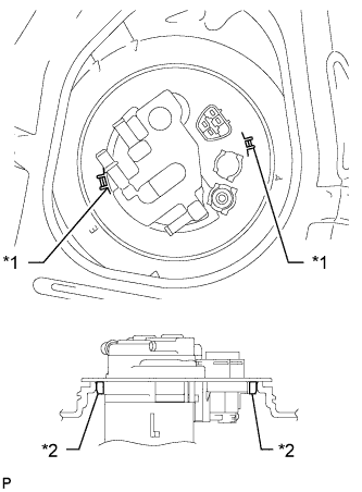
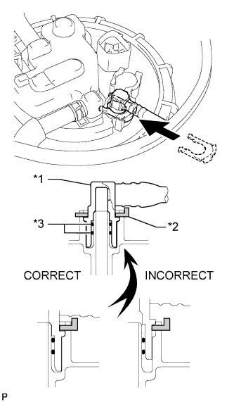
Align the protrusion of the fuel suction with pump assembly with the notch of the fuel tank.
Text in Illustration *1 Notch *2 Protrusion -
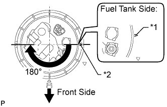
Text in Illustration *1 Start Mark
(Fuel Tank)
*2 Start Mark
(Retainer)
While holding the fuel suction with pump assembly by hand to prevent it from tilting, align the starting marks on the fuel pump gauge retainer and fuel tank and tighten the fuel pump gauge retainer 180° by hand.
Tech Tips
-
Check that there is no damage, dents, foreign matter, or other defects on the threads of the fuel tank.
-
The diameter of a supplied fuel pump gauge retainer is larger than that of the factory-installed retainer, anticipating that the fuel tank swells and expands over time. If the diameter of the factory-installed retainer is too small to reinstall, use a supplied fuel pump gauge retainer.
-
-
Set the fuel pump gauge retainer on the fuel tank. While holding the fuel suction with pump and gauge tube, tighten the retainer one complete turn by hand.
-
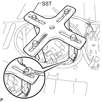
Temporarily install SST (plate and 4 claws) to the fuel pump gauge retainer.
- SST
- 09808-14030
- 09808-01070
Tech Tips
-
Be sure to use 4 SST (claws) as shown in the illustration.
-
Engage SST (claws) securely with the fuel pump gauge retainer ribs to secure SST.
-
While pressing SST (claws) against the fuel pump gauge retainer ribs securely, install the 4 bolts.
Tech Tips
Install SST while pressing SST (claws) against the fuel pump gauge retainer (toward the center of SST).
-
Install SST (handle).
-
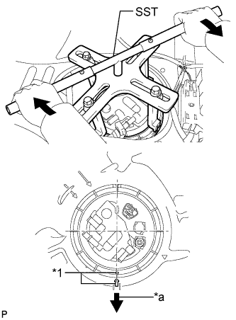
Text in Illustration *1 Mark *a Front Side Tighten the fuel pump gauge retainer approximately 270° so that the start mark on the retainer is in the position shown in the illustration.
Note
-
Do not use any tools other than those specified in this operation. Damage to the fuel pump gauge retainer or fuel tank may result.
-
Do not press down on SST excessively as this may make the fuel pump gauge retainer hard to rotate, and may damage components.
-
Make sure to rotate SST (handle) horizontally. If SST (handle) is rotated at an angle, SST may come off.
-
Do not spin SST too fast or use an impact wrench as this may result in damage to components.
-
If SST comes off of the fuel pump gauge retainer, loosen SST (bolts) and reinstall SST.
Tech Tips
The ribs on the fuel pump gauge retainer can be fitted into the tips of SST.
-
-
-
CONNECT NO. 2 FUEL TANK EVAPORATION TUBE
-
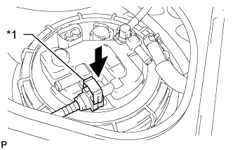
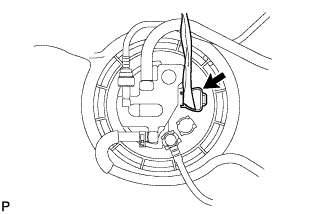
Text in Illustration *1 Retainer Connect the No. 2 fuel tank evaporation tube to the fuel suction with pump assembly.
-
-
CONNECT NO. 1 CHARCOAL CANISTER OUTLET HOSE
-
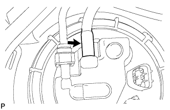
Connect the No. 1 charcoal canister outlet hose to the fuel suction with pump assembly.
Tech Tips
After connecting the No. 2 fuel tank evaporation tube and No. 1 charcoal canister outlet hose, check that the No. 2 fuel tank evaporation tube is positioned below the No. 1 charcoal canister outlet hose.
-
-
CONNECT NO. 1 FUEL EVAPORATION TUBE SUB-ASSEMBLY
-
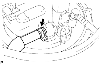
Connect the No. 1 fuel evaporation tube sub-assembly to the fuel suction with pump assembly with the clip.
-
-
CONNECT FUEL TANK MAIN TUBE SUB-ASSEMBLY
-
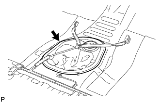
Text in Illustration *1 Fuel Tube Joint *2 Tube Joint Clip *3 O-Ring Push the fuel tube joint into the plug of the fuel suction with pump assembly, and then install the tube joint clip.
Note
-
Check that there are no scratches or foreign objects around the connected part of the fuel tube joint and plug before performing this work.
-
Check that the fuel tube joint is securely and fully inserted.
-
Check that the tube joint clip is on the collar of the fuel tube joint.
-
After installing the tube joint clip, check that the fuel tank main tube cannot be pulled out.
-
-
Connect the fuel pump connector.
-
-
CONNECT CABLE TO NEGATIVE BATTERY TERMINAL
Note
When disconnecting the cable, some systems need to be initialized after the cable is reconnected Click here.
-
INSPECT FOR FUEL LEAK
-
Make sure that there are no fuel leaks after performing maintenance on the fuel system.
-
Connect the intelligent tester to the DLC3.
-
Turn the ignition switch to ON, and push the intelligent tester main switch on.
Note
Do not start the engine.
-
Enter the following menus: Powertrain / Engine and ECT / Active Test / Control the Fuel Pump / Speed.
-
Check that there are no leaks from the fuel system.
-
Turn the ignition switch off.
-
Disconnect the intelligent tester from the DLC3.
-
-
-
INSTALL REAR FLOOR SERVICE HOLE COVER
-
Install the rear floor service hole cover with new butyl tape.
-
-
INSTALL NO. 1 QUARTER WHEEL HOUSE GUSSET SUB-ASSEMBLY
-
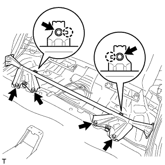
Align the 2 claws with the 2 gusset positioning holes and install the gusset with the 6 bolts.
- Torque:
- 44 N*m { 449 kgf*cm, 32 ft.*lbf }
-
-
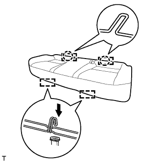
INSTALL REAR BENCH TYPE SEAT CUSHION ASSEMBLY (for Sedan)
-
Attach the 2 rear hooks of the seat cushion to the seatback.
-
Attach the 2 front hooks to install the seat cushion.
-
Confirm that the seat cushion is firmly installed.
Note
When installing the seat cushion, make sure the seat belt buckle is not under the seat cushion.
-
-
INSTALL REAR BENCH TYPE SEAT CUSHION ASSEMBLY (for Wagon)

-
Attach the 2 rear hooks of the seat cushion to the seatback.
-
Attach the 2 front hooks to install the seat cushion.
-
Confirm that the seat cushion is firmly installed.
Note
When installing the seat cushion, make sure the seat belt buckle is not under the seat cushion.
-