FUEL TANK REASSEMBLY

-
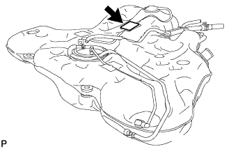
INSTALL NO. 1 EVAPORATION VENT TUBE CLAMP
-
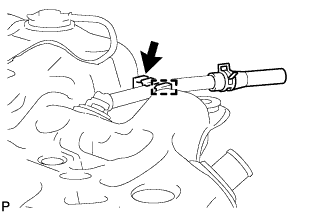
Install the No. 1 evaporation vent tube clamp and connect the hose.
-
-
INSTALL NO. 1 CHARCOAL CANISTER OUTLET HOSE
-
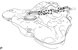
Install the No. 1 charcoal canister outlet hose and connect the 3 clamps.
-
-
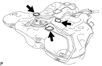
INSTALL NO. 1 FUEL EVAPORATION TUBE SUB-ASSEMBLY
-
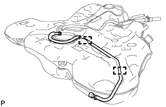
Install the No. 1 fuel evaporation tube and connect the 2 clamps.
-
-
INSTALL FUEL TANK MAIN TUBE SUB-ASSEMBLY
-
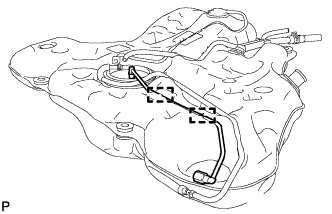
Install the fuel tank main tube and connect the 2 clamps.
-
-
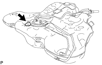
INSTALL NO. 1 FUEL TANK CUSHION
-
Install the cushion.
-
-
INSTALL NO. 4 FUEL TANK CUSHION
-
Install the cushion.
-
-
INSTALL NO. 2 FUEL TANK CUSHION
-
Install the 3 cushions.
-
-
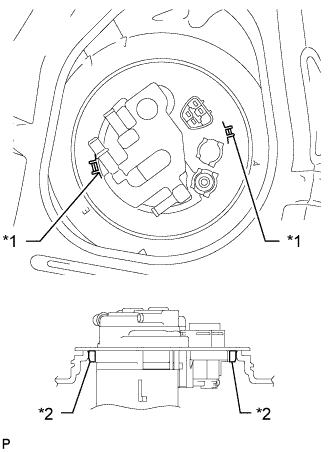
INSPECT FUEL PUMP GAUGE RETAINER
-
Inspect the fuel pump gauge retainer.
-
Install the fuel pump gauge retainer to the fuel tank by hand with the fuel suction with pump assembly disconnected.
-
If the fuel pump gauge retainer can be turned 180° or more by hand, reuse the retainer.
-
If the fuel pump gauge retainer cannot be turned 180° or more by hand, replace it with a new one.
Tech Tips
Check that there is no damage, dents, foreign matter, or other defects on the threads of the fuel tank.
-
-
-
-
INSTALL FUEL SUCTION WITH PUMP ASSEMBLY
-
Text in Illustration *1 New Gasket Install a new gasket onto the fuel tank.
-
Set the fuel suction with pump assembly to the fuel tank.
Note
Make sure that the fuel sender gauge arm does not bend.
-
Align the protrusion of the fuel suction with pump assembly with the notch of the fuel tank.
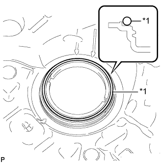
Text in Illustration *1 Notch *2 Protrusion -
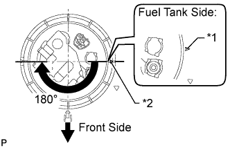
Text in Illustration *1 Start Mark
(Fuel Tank)
*2 Start Mark
(Retainer)
While holding the fuel suction with pump assembly by hand to prevent it from tilting, align the starting marks on the fuel pump gauge retainer and fuel tank and tighten the fuel pump gauge retainer 180° by hand.
Tech Tips
-
Check that there is no damage, dents, foreign matter, or other defects on the threads of the fuel tank.
-
The diameter of a supplied fuel pump gauge retainer is larger than that of the factory-installed retainer, anticipating that the fuel tank swells and expands over time. If the diameter of the factory-installed retainer is too small to reinstall, use a supplied fuel pump gauge retainer.
-
-
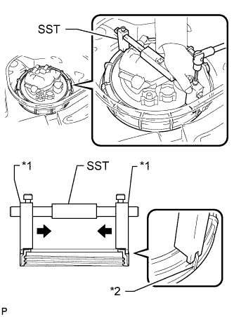
Text in Illustration *1 Claw *2 Rib Using a 6 mm socket hexagon wrench, set SST to the fuel pump gauge retainer.
- SST
- 09808-14020
Tech Tips
-
Attach SST claws securely with the fuel pump gauge retainer ribs to secure SST.
-
Install SST while pressing SST claws toward the fuel pump gauge retainer (toward the center of SST).
-
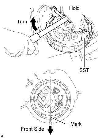
Tighten the fuel pump gauge retainer approximately 270° so that the start mark on the retainer is in the position shown in the illustration.
- SST
- 09808-14020
Note
-
Do not use any tools other than specified in this operation. Damage to the fuel pump gauge retainer or the fuel tank may result.
-
Tighten the retainer by turning it clockwise while holding SST down. Do not allow the protrusions of the fuel suction with pump to slip out of their notches on the fuel tank.
Tech Tips
The ribs on the fuel pump gauge retainer can be fitted into the tips of SST.
-