FUEL INJECTOR INSTALLATION

-
INSTALL FUEL INJECTOR ASSEMBLY
-

Text in Illustration *1 O-Ring Apply a light coat of gasoline or spindle oil to new O-rings and install one onto each fuel injector.
-
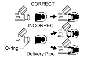
Apply a light coat of gasoline or spindle oil to the part of the fuel delivery pipe which comes into contact with the O-ring of the fuel injector.
-
Apply a light coat of gasoline or spindle oil to the O-ring again and install the fuel injectors onto the fuel delivery pipe.
Note
Make sure that the O-ring is not cracked or jammed when installing.
-
Check that the fuel injector rotates smoothly.
If the fuel injector does not rotate, replace the O-ring.
-
-
INSTALL FUEL DELIVERY PIPE SUB-ASSEMBLY
-
Install 4 new insulators to the cylinder head.
-
Install the 2 delivery pipe spacers to the cylinder head.
-
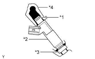
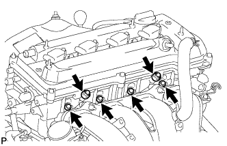
Text in Illustration *1 O-Ring *2 Fuel Injector *3 Insulator *4 Fuel Delivery Pipe Install the fuel delivery pipe together with the 4 fuel injectors, and then temporarily install the 2 bolts.
Note
Be careful not to drop the fuel injectors when installing the fuel delivery pipe.
-
Check that the fuel injector rotates smoothly.
If the fuel injector does not rotate, replace the O-ring.
-
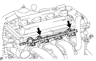
Tighten the 2 bolts.
- Torque:
- 20 N*m { 204 kgf*cm, 15 ft.*lbf }
-
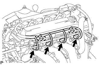
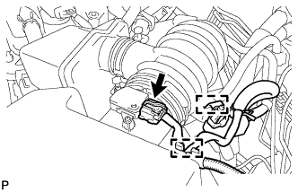
Connect the 4 fuel injector connectors.
-
Connect the 2 wire harness clamps.
-
-
CONNECT NO. 2 VENTILATION HOSE
-
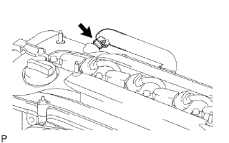
Connect the ventilation hose to the ventilation valve.
-
-
CONNECT FUEL TUBE
-
Connect the fuel tube.
-
Push the fuel tube connector until it makes a "click" sound.
-
Install the fuel pipe clamp.
-
Install the fuel tube to the fuel hose clamp.
-
-
-
INSTALL AIR CLEANER CAP AND HOSE
-
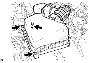
Insert the hinge part of the air cleaner cap and hose into the air cleaner case, and then fasten the 3 hook clamps.
-
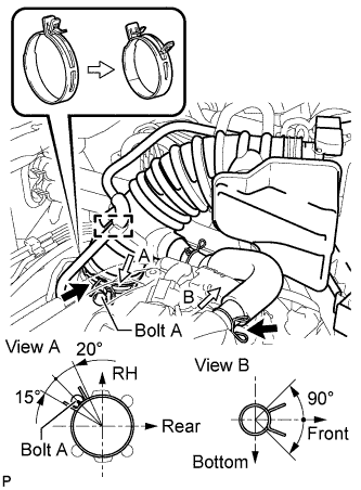
Align the matchmarks of the No. 1 air cleaner hose and throttle body. Then connect the No. 1 air cleaner hose to the throttle body and push apart the tabs of the No. 1 air cleaner hose clamp.
Note
Make sure that the hose clamp is at the correct angle.
-
Connect the No. 2 fuel vapor feed hose to the air cleaner hose.
-
Connect the No. 2 ventilation hose to the air cleaner hose.
-
Connect the purge VSV.
-
Connect the wire harness and mass air flow meter connector.
-
-
INSTALL NO. 1 ENGINE COVER SUB-ASSEMBLY
-
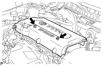
Install the cover with the 2 nuts.
- Torque:
- 9.0 N*m { 92 kgf*cm, 80 in.*lbf }
-
-
CONNECT CABLE TO NEGATIVE BATTERY TERMINAL
Note
When disconnecting the cable, some systems need to be initialized after the cable is reconnected Click here.
-
INSTALL ENGINE ROOM SIDE COVER
-
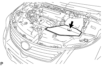
Install the engine room side cover with the clip.
-
-
INSPECT FOR FUEL LEAK
-
Make sure that there are no fuel leaks after performing maintenance on the fuel system.
-
Connect the intelligent tester to the DLC3.
-
Turn the engine switch on (IG) and push the intelligent tester main switch on.
Note
Do not start the engine.
-
Select the Active Test mode on the intelligent tester.
Tech Tips
Refer to the intelligent tester operator's manual for further details.
-
Check that there are no leaks from the fuel system.
-
Turn the engine switch off.
-
Disconnect the intelligent tester from the DLC3.
-
-