CAN COMMUNICATION SYSTEM Power Steering ECU Communication Stop Mode
DESCRIPTION
| Detection Item | Symptom | Trouble Area |
|---|---|---|
| Power steering ECU Communication Stop Mode | Either condition is met:
|
|
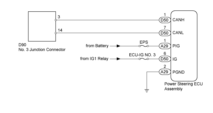
WIRING DIAGRAM
INSPECTION PROCEDURE
Note
Inspect the fuses for circuits related to this system before performing the following inspection procedure.
Tech Tips
Operating the ignition switch, any switches or any doors triggers related ECU and sensor communication with the CAN, which causes resistance variation.
PROCEDURE
-
DISCONNECT CABLE FROM NEGATIVE BATTERY TERMINAL
-
Disconnect the cable from the negative (-) battery terminal before measuring the resistances of the main wire and branch wire.
CAUTION:
Wait at least 90 seconds after disconnecting the cable from the negative (-) battery terminal to disable the SRS system.
Note
-
w/ Navigation System (for HDD):
After the ignition switch is turned off, the HDD navigation system requires approximately a minute to record various types of memory and settings. As a result, after turning the ignition switch off, wait a minute or more before disconnecting the cable from the negative (-) battery terminal.
-
When disconnecting the cable, some systems need to be initialized after the cable is reconnected Click here.
-
NEXT 
-
-
CHECK FOR OPEN IN CAN BUS WIRE (POWER STEERING ECU BRANCH WIRE)
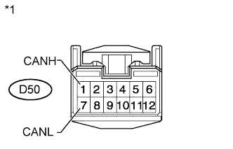
Text in Illustration *1 Front view of wire harness connector
(to Power Steering ECU Assembly)
-
Disconnect the D50 power steering ECU assembly connector.
-
Measure the resistance according to the value(s) in the table below.
Standard Resistance Tester Connection Switch Condition Specified Condition D50-1 (CANH) - D50-7 (CANL) Ignition switch off 54 to 69 Ω
NG 
REPAIR OR REPLACE AFS ECU BRANCH WIRE OR CONNECTOR (CANH, CANL)
OK
-
-
CHECK HARNESS AND CONNECTOR (POWER STEERING ECU - BATTERY AND BODY GROUND)
-
Connect the cable to the negative (-) battery terminal.
Note
When disconnecting the cable, some systems need to be initialized after the cable is reconnected Click here.
-
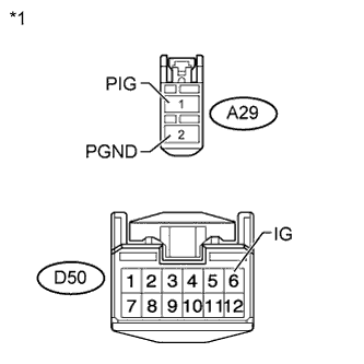
Text in Illustration *1 Front view of wire harness connector
(to Power Steering ECU Assembly)
Disconnect the A29 and D50 power steering ECU assembly connectors.
-
Measure the resistance according to the value(s) in the table below.
Standard Resistance Tester Connection Condition Specified Condition A29-2 (PGND) - Body ground Always Below 1 Ω -
Measure the voltage according to the value(s) in the table below.
Standard Voltage Tester Connection Switch Condition Specified Condition A29-1 (PIG) - Body ground Always 11 to 14 V D50-6 (IG) - Body ground Ignition switch ON 11 to 14 V Result Result Proceed to OK (for LHD) A OK (for RHD) B NG C
B
REPLACE POWER STEERING ECU ASSEMBLY Click here
C
REPAIR OR REPLACE HARNESS OR CONNECTOR
A 
REPLACE POWER STEERING ECU ASSEMBLY Click here
-