POWER MANAGEMENT CONTROL ECU INSTALLATION

-
INSTALL POWER MANAGEMENT CONTROL ECU (for LHD)
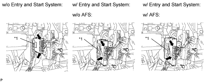
Text in Illustration *1 Label
-
w/o Entry and Start System:
Install the power management control ECU with the bolt.
- Torque:
- 8.0 N*m { 82 kgf*cm, 71 in.*lbf }
-
w/ Entry and Start System:
Install the power management control ECU with the 2 bolts.
- Torque:
- 8.0 N*m { 82 kgf*cm, 71 in.*lbf }
Tech Tips
First install the upper bolt, and then install the lower bolt.
-
Connect the 2 connectors.
-
-
INSTALL GLOVE COMPARTMENT DOOR ASSEMBLY (for LHD)
-
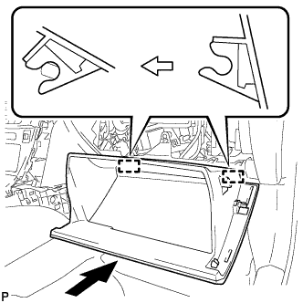
Attach the 2 hinges to install the door.
-
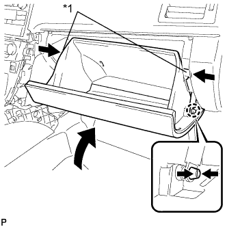
Text in Illustration *1 Stopper While pushing in the sides of the glove compartment door as indicated by the arrows in the illustration, close the door to engage the 2 stoppers.
-
-
INSTALL POWER MANAGEMENT CONTROL ECU (for RHD)
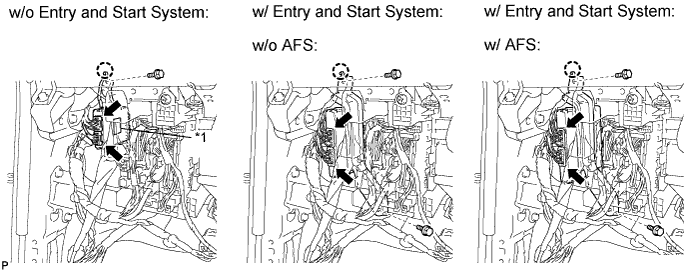
Text in Illustration *1 Label
-
w/o Entry and Start System:
Align the power management control ECU positioning hole with the claw, and install the power management control ECU with the bolt.
- Torque:
- 8.0 N*m { 82 kgf*cm, 71 in.*lbf }
-
w/ Entry and Start System:
Align the power management control ECU positioning hole with the claw, and install the power management control ECU with the 2 bolts.
- Torque:
- 8.0 N*m { 82 kgf*cm, 71 in.*lbf }
Tech Tips
First install the lower bolt, and then install the upper bolt.
-
Connect the 2 connectors.
-
-
INSTALL UPPER INSTRUMENT PANEL SUB-ASSEMBLY (for RHD)
-
Install the upper instrument panel sub-assembly Click here.
-