GENERATOR REASSEMBLY

-
INSTALL GENERATOR ROTOR BEARING
-
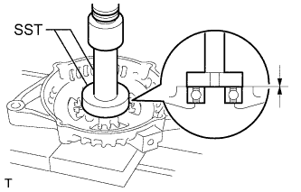
Using SST and a press, press in a new generator rotor bearing.
- SST
- 09950-60010 ( 09951-00470 )
- 09950-70010 ( 09951-07100 )
-
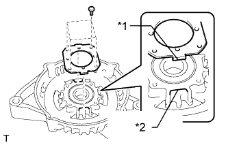
Text in Illustration *1 Tab *2 Cutout Fit the tabs on the retainer plate into the cutouts on the drive end frame to install the retainer plate.
-
Install the 4 screws.
- Torque:
- 2.3 N*m { 23 kgf*cm, 20 in.*lbf }
-
-
INSTALL GENERATOR ROTOR ASSEMBLY
-
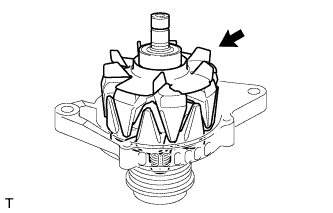
Place the drive end frame on the generator with clutch pulley.
-
Install the generator rotor to the generator drive end frame.
-
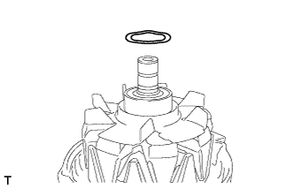
Install the washer to the generator rotor.
-
-
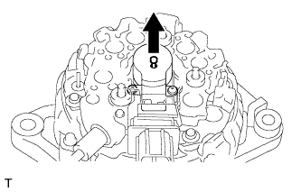
INSTALL GENERATOR COIL ASSEMBLY
-
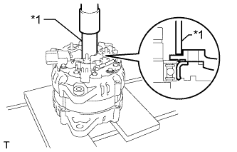
Text in Illustration *1 21 mm Deep Socket Wrench Using a 21 mm deep socket wrench and a press, slowly press on the generator coil to install it.
-
Install the 4 bolts.
- Torque:
- 5.9 N*m { 60 kgf*cm, 52 in.*lbf }
-
-
INSTALL GENERATOR BRUSH HOLDER ASSEMBLY
-
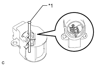
Text in Illustration *1 Pin While pushing the 2 brushes into the generator brush holder, insert a pin with a diameter of 1.0 mm (0.0394 in.) into the brush holder hole.
-
Install the generator brush holder to the generator coil with the 2 screws.
- Torque:
- 1.8 N*m { 18 kgf*cm, 16 in.*lbf }
-
Pull out the pin from the generator brush holder.
-
-
INSTALL TERMINAL INSULATOR
-
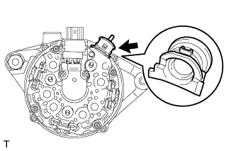
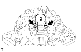
Install the terminal insulator to the generator coil.
Note
Pay attention to the installation direction of the terminal insulator.
-
-
INSTALL GENERATOR REAR END COVER
-
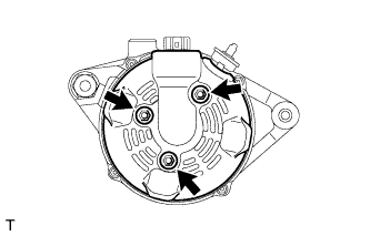
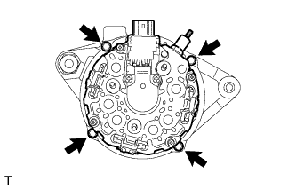
Install the generator rear end cover to the generator coil with the 3 nuts.
- Torque:
- 4.6 N*m { 46 kgf*cm, 40 in.*lbf }
-
-
INSTALL GENERATOR WITH CLUTCH PULLEY
-
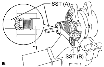
Text in Illustration *1 Rotor Shaft Temporarily install the generator with clutch pulley by hand.
-
Mount the generator in a vise between aluminum plates.
-
Install SST (A) and (B) to the generator with clutch pulley as shown in the illustration.
- SST
- 09820-63021
Note
Securely attach SST to the generator with clutch pulley and generator rotor shaft.
-
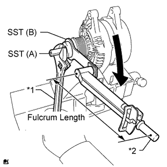
Text in Illustration *1 Hold *2 Turn Using a wrench to hold SST (A), turn SST (B) clockwise to tighten the generator with clutch pulley.
- Torque:
- without SST
- 80 N*m { 816 kgf*cm, 59 ft.*lbf }
- with SST
- 64 N*m { 653 kgf*cm, 47 ft.*lbf }
Note
-
Be careful as the generator with clutch pulley or generator rotor shaft may be damaged if the position of SST is not securely maintained while performing this operation.
-
Use a torque wrench with a fulcrum length of 400 mm (15.7 in.).
-
This torque value is effective when SST is parallel to the torque wrench.
-
Remove SST from the generator.
-
Check that the generator with clutch pulley rotates smoothly.
-
-
INSTALL GENERATOR PULLEY CAP
-
Install a new generator pulley cap to the generator with clutch pulley.
-