CHARGING SYSTEM, Diagnostic DTC:P0516, P0517

| DTC Code | DTC Name |
|---|---|
| P0516 | Battery Temperature Sensor Circuit Low |
| P0517 | Battery Temperature Sensor Circuit High |
DESCRIPTION
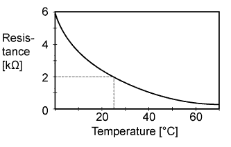
The battery temperature sensor detects the battery temperature. The battery current sensor assembly has a built-in thermistor with a resistance that changes in response to changes in the battery temperature. When the battery temperature is low the thermistor resistance increases, and when the temperature is high the resistance decreases. The battery temperature sensor is connected to the power management control ECU. A 5 V power supply voltage is supplied to the battery temperature sensor from terminal THB of the power management control ECU via resistor R. As resistor R and the battery temperature sensor are connected in series, when the resistance changes in response to changes in the battery temperature, the electric potential at terminal THB also changes. Based on this signal, the power management control ECU protects the battery by reducing the charge current when the battery temperature is high.
| DTC Code | DTC Detection Condition | Trouble Area |
|---|---|---|
| P0516 | When the ignition switch is ON, the battery temperature sensor output is 0.2 V or less for 0.5 seconds or more (1 trip detection logic). |
|
| P0517 | When the ignition switch is ON, the battery temperature sensor output is 4.8 V or higher for 0.5 seconds or more (1 trip detection logic). |
|
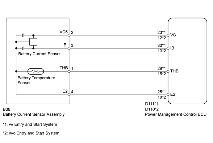
WIRING DIAGRAM
INSPECTION PROCEDURE
PROCEDURE
-
CHECK BATTERY CURRENT SENSOR ASSEMBLY
-
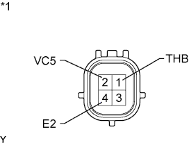
Text in Illustration *1 Component without harness connected
(Battery Current Sensor Assembly)
Disconnect the B38 battery current sensor connector.
-
Measure the resistance according to the value(s) in the table below.
Standard Resistance Tester Connection Condition Specified Condition 1 (THB) - 4 (E2) 20 to 30°C
(68 to 86°F)
1.5 to 2.5 kΩ 2 (VC5) - 4 (E2) Always 3 to 10 kΩ Result Result Proceed to OK w/ Entry and Start System A w/o Entry and Start System B NG C
B 
CHECK HARNESS AND CONNECTOR (POWER MANAGEMENT CONTROL ECU - BATTERY CURRENT SENSOR) Click here
C 
REPLACE BATTERY CURRENT SENSOR ASSEMBLY Click here
A 
-
-
CHECK HARNESS AND CONNECTOR (POWER MANAGEMENT CONTROL ECU - BATTERY CURRENT SENSOR)
w/ Entry and Start System:
-
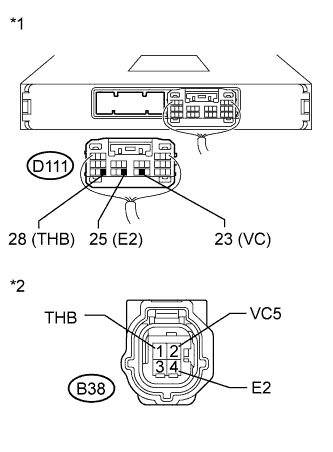
Text in Illustration *1 Rear view of wire harness connector
(to Power Management Control ECU)
*2 Front view of wire harness connector
(to Battery Current Sensor)
Disconnect the D111 power management control ECU connector.
-
Disconnect the B38 battery current sensor connector.
-
Measure the resistance according to the value(s) in the table below.
Standard Resistance Tester Connection Condition Specified Condition D111-23 (VC) - B38-2 (VC5) Always Below 1 Ω D111-25 (E2) - B38-4 (E2) D111-28 (THB) - B38-1 (THB) D111-23 (VC) - Body ground Always 10 kΩ or higher D111-25 (E2) - Body ground D111-28 (THB) - Body ground
NG
REPAIR OR REPLACE HARNESS OR CONNECTOR (POWER MANAGEMENT CONTROL ECU - BATTERY CURRENT SENSOR)
OK 
REPLACE POWER MANAGEMENT CONTROL ECU Click here
-
-
CHECK HARNESS AND CONNECTOR (POWER MANAGEMENT CONTROL ECU - BATTERY CURRENT SENSOR)
w/o Entry and Start System:
-
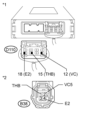
Text in Illustration *1 Rear view of wire harness connector
(to Power Management Control ECU)
*2 Front view of wire harness connector
(to Battery Current Sensor)
Disconnect the D110 power management control ECU connector.
-
Disconnect the B38 battery current sensor connector.
-
Measure the resistance according to the value(s) in the table below.
Standard Resistance Tester Connection Condition Specified Condition D110-12 (VC) - B38-2 (VC5) Always Below 1 Ω D110-18 (E2) - B38-4 (E2) D110-15 (THB) - B38-1 (THB) D110-12 (VC) - Body ground Always 10 kΩ or higher D110-18 (E2) - Body ground D110-15 (THB) - Body ground
NG
REPAIR OR REPLACE HARNESS OR CONNECTOR (POWER MANAGEMENT CONTROL ECU - BATTERY CURRENT SENSOR)
OK
REPLACE POWER MANAGEMENT CONTROL ECU Click here
-