SFI SYSTEM, Diagnostic DTC:U011B

| DTC Code | DTC Name |
|---|---|
| U011B | Lost Communication with Rocker Arm Control Module "A" |
DESCRIPTION
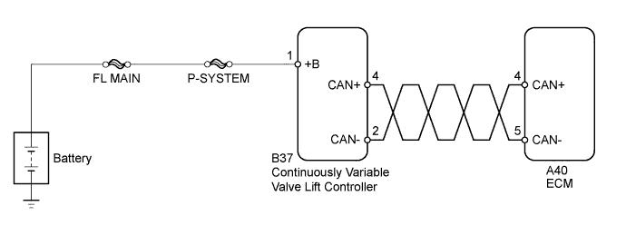
The ECM and continuously variable valve lift controller assembly send signals via CAN communication. When there is a malfunction in the CAN communication, a DTC is stored and the MIL illuminates.
| DTC No. | DTC Detection Condition | Trouble Area |
|---|---|---|
| U011B | CAN communication stops (1 trip detection logic) |
|
WIRING DIAGRAM
INSPECTION PROCEDURE
Note
When the one of the following DTCs is stored and the MIL is illuminated, DTC P1047 is stored and actuator position learning is performed every time the engine is started. Also, after the system returns to normal, the following occurs during the first driving cycle: 1) DTC P1047 is stored, 2) actuator position learning is performed and 3) the MIL illuminates during actuator position learning.
| Actuator position learning is performed when these DTCs are output. |
|---|
| P1046, P1049, P104A, P1055, P2646, P2647, P2648, P2649, P264A, U011B |
Tech Tips
-
When there is no power (+B) supplied to the continuously variable valve lift controller assembly, DTC U011B is stored. After the continuously variable valve lift controller assembly power supply system and communication lines have been connected or repaired, actuator position learning is performed and DTC P1047 is stored the next time the vehicle is driven.
-
After performing repairs, perform the following procedures and check that DTCs are not output again.
-
Connect the intelligent tester to the DLC3.
-
Start the engine and warm it up.
-
Turn the tester on.
-
Clear the DTCs Click here.
-
Turn the ignition switch off and wait 10 seconds.
-
Start the engine and idle it for 20 seconds.
-
Clear the DTCs Click here.
-
Turn the ignition switch off and wait 10 seconds.
-
Start the engine and idle it for 20 seconds.
-
Turn the ignition switch off and wait 10 seconds.
-
Turn the ignition switch to ON.
-
Enter the following menus: Powertrain / Engine and ECT / DTC.
-
Read the DTCs.
Note
Inspect the fuses for circuits related to this system before performing the following inspection procedure.
PROCEDURE
-
CHECK CONTINUOUSLY VARIABLE VALVE LIFT CONTROLLER ASSEMBLY (POWER SOURCE)
-
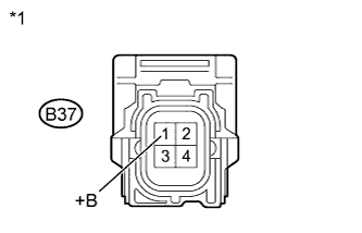
Text in Illustration *1 Component without harness connected
(Continuously Variable Valve Lift Controller)
Disconnect the continuously variable valve lift controller assembly connector.
-
Turn the ignition switch to ON.
-
Measure the voltage according to the value(s) in the table below.
Standard Voltage Tester Connection Switch Condition Specified Condition B37-1(+B) - Body ground Ignition switch ON 11 to 14 V -
Reconnect the continuously variable valve lift controller assembly connector.
NG 
REPAIR OR REPLACE HARNESS OR CONNECTOR (CONTINUOUSLY VARIABLE VALVE LIFT CONTROLLER - BATTERY)
OK 
-
-
CHECK HARNESS AND CONNECTOR (CONTINUOUSLY VARIABLE VALVE LIFT CONTROLLER - ECM)
-
Disconnect the continuously variable valve lift controller assembly connector.
-
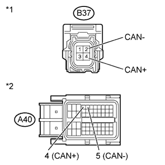
Text in Illustration *1 Front view of wire harness connector
(to Continuously Variable Valve Lift Controller)
*2 Front view of wire harness connector
(to ECM)
Disconnect the ECM connector.
-
Measure the resistance according to the value(s) in the table below.
Standard Resistance (Check for open) Tester Connection Switch Condition Specified Condition B37-4 (CAN+) - A40-4 (CAN+) Ignition switch off Below 1 Ω B37-2 (CAN-) - A40-5 (CAN-) Ignition switch off Below 1 Ω Standard Resistance (Check for short) Tester Connection Switch Condition Specified Condition B37-4 (CAN+) or A40-4 (CAN+) - Body ground Ignition switch off 10 kΩ or higher B37-2 (CAN-) or A40-5 (CAN-) - Body ground Ignition switch off 10 kΩ or higher -
Reconnect the ECM connector.
-
Reconnect the continuously variable valve lift controller assembly connector.
NG
REPAIR OR REPLACE HARNESS OR CONNECTOR (CONTINUOUSLY VARIABLE VALVE LIFT CONTROLLER - ECM)
OK
-
-
REPLACE CONTINUOUSLY VARIABLE VALVE LIFT CONTROLLER ASSEMBLY
-
Replace the continuously variable valve lift controller assembly Click here.
NEXT
-
-
PERFORM SIMULATION TEST
-
Connect the intelligent tester to the DLC3.
-
Turn the ignition switch to ON.
-
Turn the tester on.
-
Clear the DTC Click here.
-
Perform a simulation test.
-
Turn the ignition switch to ON and wait 5 seconds
-
Start the engine and idle it for 5 seconds.
-
Turn the ignition switch to off and wait 5 seconds
-
-
Turn the ignition switch to ON.
-
Turn the tester on.
-
Enter the following menus: Powertrain / Engine and ECT / DTC.
-
Read the DTCs.
Result Result Proceed to DTC U011B is output A DTC is not output B
B
END
A 
REPLACE ECM Click here
-