SFI SYSTEM, Diagnostic DTC:P0724

| DTC Code | DTC Name |
|---|---|
| P0724 | Brake Switch "B" Circuit High |
DESCRIPTION
This DTC indicates that the stop light switch remains ON. When the stop light switch remains ON during GO and STOP driving, the ECM interprets this as a fault in the stop light switch. Then the MIL illuminates and the ECM stores the DTC.
| DTC No. | DTC Detection Condition | Trouble Area |
|---|---|---|
| P0724 | Stop light switch remains ON even when vehicle is driven in GO (30 km/h (18.63 mph) or more) and STOP (less than 3 km/h (1.86 mph)) pattern 5 times (2 trip detection logic) |
|
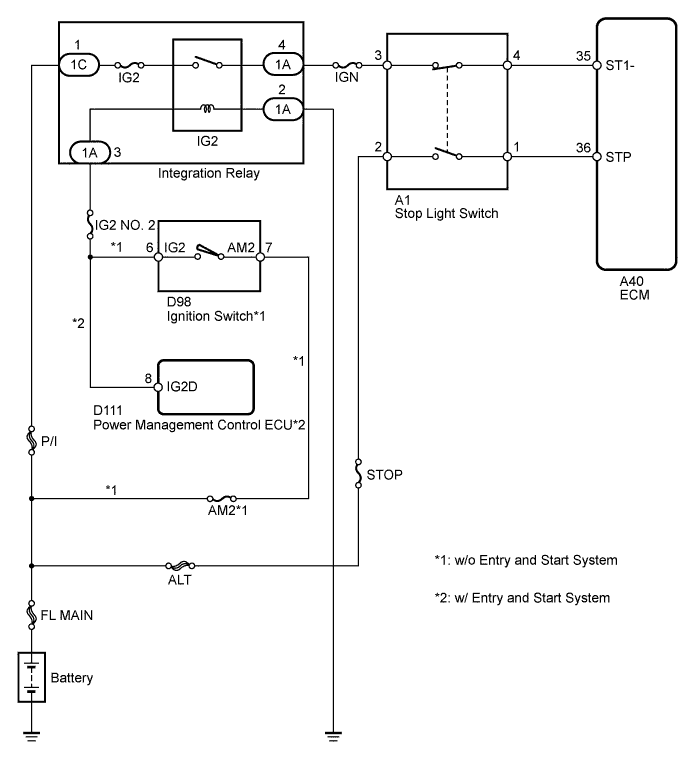
WIRING DIAGRAM
INSPECTION PROCEDURE
Note
Inspect the fuses for circuits related to this system before performing the following inspection procedure.
Tech Tips
-
Using the intelligent tester's Data List allows switch, sensor, actuator and other item values to be read without removing any parts. Reading the Data List early in troubleshooting is one way to save time.
-
Read freeze frame data using the intelligent tester. The ECM records vehicle and driving condition information as freeze frame data the moment a DTC is stored. When troubleshooting, freeze frame data can help determine if the vehicle was moving or stationary, if the engine was warmed up or not, if the air fuel ratio was lean or rich, and other data from the time the malfunction occurred.
PROCEDURE
-
READ VALUE USING INTELLIGENT TESTER (STOP LIGHT SWITCH)
-
Connect the intelligent tester to the DLC3.
-
Turn the ignition switch to ON.
-
Turn the tester on.
-
Enter the following menus: Powertrain / Engine and ECT / Data List / Stop Light Switch.
-
Read the value displayed on the tester when the depressed and released brake pedal.
OK Brake Pedal Display Released OFF Depressed ON
NG 
INSPECT STOP LIGHT SWITCH ASSEMBLY Click here
OK 
CHECK FOR INTERMITTENT PROBLEMS Click here
-
-
INSPECT STOP LIGHT SWITCH ASSEMBLY
-
Disconnect the stop light switch assembly connector.
-
Remove the stop light switch assembly.
-
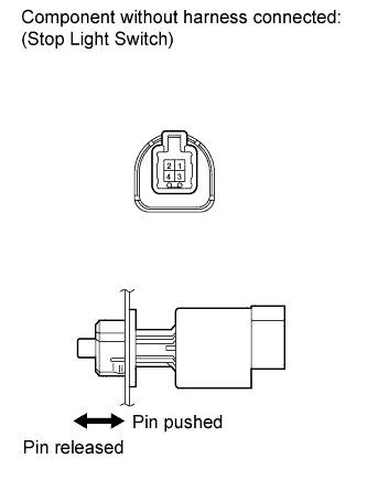
Measure the resistance according to the value(s) in the table below.
Standard Resistance Tester Connection Switch Condition Specified Condition 1 - 2 Switch pin not pushed Below 1 Ω Switch pin pushed 10 kΩ or higher 3 - 4 Switch pin not pushed 10 kΩ or higher Switch pin pushed Below 1 Ω -
Reinstall the stop light switch assembly.
-
Reconnect the stop light switch assembly connector.
NG 
REPLACE STOP LIGHT SWITCH ASSEMBLY Click here
OK 
-
-
CHECK HARNESS AND CONNECTOR (ECM - STOP LIGHT SWITCH ASSEMBLY)
-
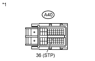
Text in Illustration *1 Front view of wire harness connector
(to ECM)
Disconnect the ECM connector.
-
Measure the voltage according to the value(s) in the table below.
Standard Voltage Tester Connection Condition Specified Condition A40-36 (STP) - Body ground Brake pedal is depressed 11 to 14 V A40-36 (STP) - Body ground Brake pedal is released Below 1.5 V -
Reconnect the ECM connector.
NG
REPAIR OR REPLACE HARNESS OR CONNECTOR (ECM - STOP LIGHT SWITCH ASSEMBLY)
OK
REPLACE ECM Click here
-