ECM INSTALLATION

-
INSTALL ECM
-
Install the No. 1 ECM bracket and No. 2 ECM bracket to the ECM with the 4 screws.
- Torque:
- 3.0 N*m { 31 kgf*cm, 27 in.*lbf }
-
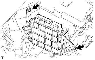
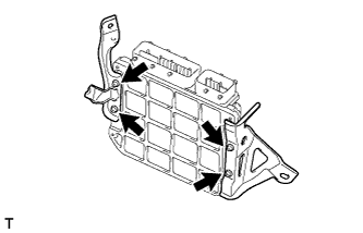
Install the ECM with the 2 bolts.
- Torque:
- 13 N*m { 127 kgf*cm, 9 ft.*lbf }
-
Connect the 2 ECM connectors.
-
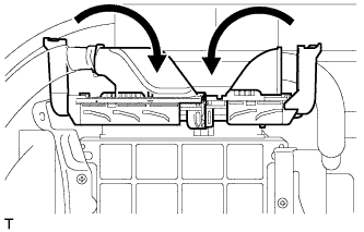
Connect the 2 ECM connectors and lower the 2 levers.
Note
-
When connecting the connectors, make sure that dirt, water or other foreign matter does not get caught between the connectors and other parts.
-
Make sure that the 2 levers are securely lowered.
-
-
-
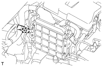
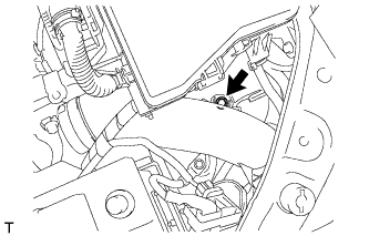
Connect the wire harness clamp.
-
-
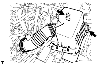
CONNECT NO. 2 AIR CLEANER INLET
-
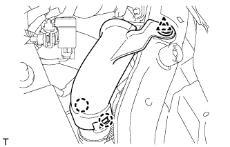
Connect the No. 2 air cleaner inlet to the vehicle body with the bolt.
- Torque:
- 7.0 N*m { 71 kgf*cm, 62 in.*lbf }
-
-
INSTALL NO. 1 AIR CLEANER INLET
-
Attach the 2 claws to install the No. 1 air cleaner inlet.
-
Install the clip.
-
-
INSTALL AIR CLEANER CASE SUB-ASSEMBLY
-
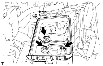
Install the air cleaner case with the 3 bolts.
- Torque:
- 7.0 N*m { 71 kgf*cm, 62 in.*lbf }
-
Attach the wire harness clamp to the air cleaner case.
-
-
INSTALL AIR CLEANER CAP SUB-ASSEMBLY
-
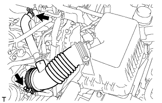
Connect the air cleaner cap with the band.
-
Connect the ventilation hose.
-
Connect the 2 clamps.
-
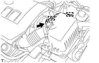
Attach the wire harness to the 2 clamps.
-
Connect the mass air flow meter connector.
-
-
INSTALL NO. 2 CYLINDER HEAD COVER
-
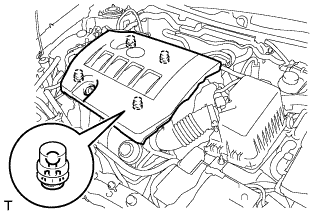
Attach the 4 clips to install the cover.
Note
-
Be sure to attach the clips securely.
-
Do not apply excessive force or hit the cover to attach the clips. This may cause the cover to break.
-
-
-
CONNECT CABLE TO NEGATIVE BATTERY TERMINAL
Note
When disconnecting the cable, some systems need to be initialized after the cable is reconnected Click here.
-
INSTALL RADIATOR SUPPORT OPENING COVER
-
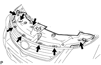
Install the radiator support opening cover with the 8 clips.
-
-
INSTALL ENGINE ROOM SIDE COVER
-

Install the engine room side cover with the clip.
-
-
PERFORM INITIALIZATION
Note
-
Be sure to perform this procedure after reassembling the throttle body assembly or removing and reinstalling any throttle body component.
-
Perform the following procedure after replacing the ECM, throttle body assembly or any throttle body components. The following procedure should also be performed if the throttle body is cleaned.
-
Be sure to perform this procedure after replacing the ECM and reconnecting the battery cable.
-
Disconnect the EFI MAIN and ETCS fuses at the same time. Wait at least 60 seconds, and then reconnect the fuses.
-
Turn the ignition switch to ON without operating the accelerator pedal.
Note
If the accelerator pedal is operated, perform the above steps again.
-
Connect the intelligent tester to the DLC3 and clear the DTCs Click here.
-
Start the engine and check that the MIL is not illuminated and that the idle speed is within the specified range when the A/C is switched off after the engine is warmed up.
Standard idle speed 580 to 680 rpm Note
-
Be sure to perform this step with all accessories off.
-
Make sure that the shift lever is in neutral.
-
-
Enter the following menus: Powertrain / Engine and ECT / Data List / All Data / Throttle Sensor Position. Fully depress the accelerator pedal and check that the value is 60% or more.
-
Perform a road test and confirm that there are no abnormalities.
-