CONTINUOUSLY VARIABLE VALVE LIFT CONTROLLER INSTALLATION

-
INSTALL CONTINUOUSLY VARIABLE VALVE LIFT CONTROLLER ASSEMBLY
-
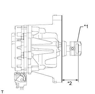
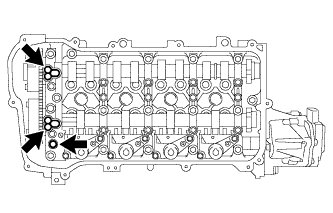
Text in Illustration *1 Connector *2 Protruding Distance Measure the protruding distance of the continuously variable valve lift controller assembly.
Tech Tips
-
When reinstalling the continuously variable valve lift controller assembly, perform the measurement after the valve lift control actuator connector is installed.
-
It is not necessary to perform this measurement when installing a new continuously variable valve lift controller assembly as the protruding distance is 34.57 to 34.73 mm (1.36 to 1.37 in.).
Standard protruding distance 34.57 to 34.73 mm (1.36 to 1.37 in.) If the protruding distance of the continuously variable valve lift controller assembly is not 34.57 to 34.73 mm (1.36 to 1.37 in.), perform the Active Test and adjust the protruding distance to the specified value Click here.
-
-
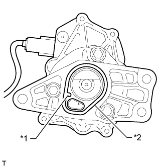
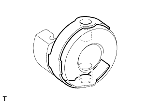
Text in Illustration *1 Protrusion *2 New O-Ring Install a new O-ring to the continuously variable valve lift controller assembly.
Note
-
Align the protrusion of the O-ring with the protrusion of the continuously variable valve lift controller assembly.
-
Make sure that the O-ring is not protruding from the groove in the continuously variable valve lift controller assembly.
-
-
Rotate the crankshaft clockwise to retract the valve rocker shaft.
-
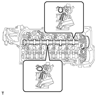
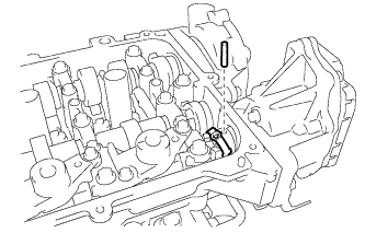
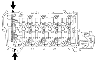
Rotate the crankshaft clockwise again until the intake camshaft position at the No. 1 cylinder and No. 3 cylinder is as shown in the illustration.
-
Install the valve lift control actuator connector clip to the valve lift control actuator connector.
Note
Be sure to insert the protrusions of the valve lift control actuator connector clip into the holes in the valve lift control actuator connector.
Tech Tips
When the continuously variable valve lift controller assembly is new, a valve lift control actuator connector is attached to it. Remove the valve lift control actuator connector before performing these procedures.
-
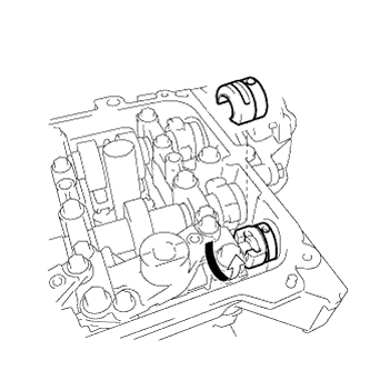
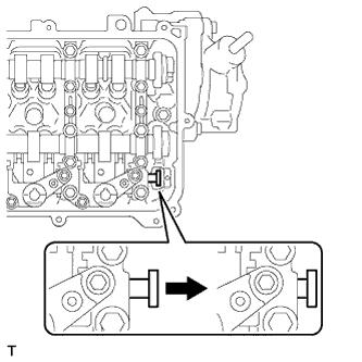
Install the valve lift control actuator connector to the valve rocker shaft and rotate the valve lift control actuator connector as shown in the illustration.
-
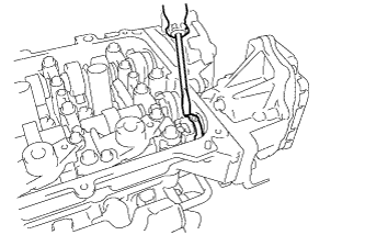
Insert the continuously variable valve lift controller assembly into the camshaft housing.
-
Place the wire harness clamp bracket onto the stud bolts.
-
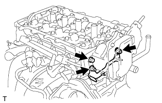
Install the continuously variable valve lift controller assembly to the camshaft housing with the bolt and 2 nuts.
- Torque:
- 18 N*m { 184 kgf*cm, 13 ft.*lbf }
Note
Make sure the O-ring is not caught between the parts.
-
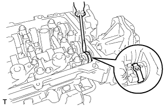
Using a screwdriver, slide the valve lift control actuator connector clip from the valve lift control actuator connector.
Note
Slide only the upper part of the valve lift control actuator connector clip as the straight pin falls out from the bottom if the valve lift control actuator connector clip is completely removed.
-
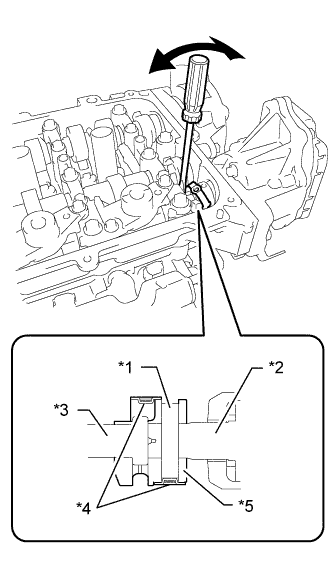
Text in Illustration *1 Straight Pin *2 Controller Shaft *3 Rocker Shaft *4 Clip *5 Connector Using a screwdriver, lightly pry the valve lift control actuator connector and align the hole in the valve lift control actuator connector with the hole in the continuously variable valve lift controller assembly.
Note
-
Do not forcefully pry the valve lift control actuator connector.
-
Do not damage the camshaft housing or camshaft bearing cap.
-
-
Insert the straight pin into the valve lift control actuator connector.
Note
Do not use a tool to insert the straight pin. Insert the straight pin by hand.
Tech Tips
If the straight pin is difficult to insert, insert the pin while lightly prying the valve lift control actuator connector.
-
Using a screwdriver, install the valve lift control actuator connector clip to the valve lift control actuator connector.
Note
Insert the protrusion of the valve lift control actuator connector clip into the hole in the valve lift control actuator connector.
-
-
INSTALL CYLINDER HEAD COVER GASKET
-
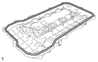
Install a new cylinder head cover gasket to the cylinder head cover.
Note
Remove any oil from the contact surfaces.
-
-
INSTALL CYLINDER HEAD COVER SUB-ASSEMBLY
-
Install 3 new gaskets to the camshaft bearing cap.
-
Apply seal packing as shown in the illustration.
Seal packing Toyota Genuine Seal Packing Black, Three Bond 1207B or equivalent Standard diameter 4.0 mm (0.157 in.) Note
-
Remove any oil from the contact surfaces.
-
Install the cylinder head cover sub-assembly within 3 minutes and tighten the bolts within 15 minutes after applying seal packing.
-
Do not start the engine for at least 2 hours after the installation.
-
-
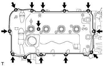
Install the cylinder head cover with a new seal washer and the 13 bolts.
- Torque:
- 10 N*m { 102 kgf*cm, 7 ft.*lbf }
-
-
INSTALL AIR TUBE
-
Install the air tube with the 2 bolts.
- Torque:
- 10 N*m { 102 kgf*cm, 7 ft.*lbf }
-
Connect the No. 2 air hose and No. 1 fuel vapor feed hose.
-
Connect the 2 union to connector tube hoses.
-
Connect the fuel vapor feed hose to the purge VSV.
-
-
INSTALL IGNITION COIL ASSEMBLY
-
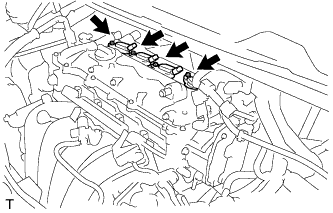
Install the 4 ignition coils with the 4 bolts.
- Torque:
- 10 N*m { 102 kgf*cm, 7 ft.*lbf }
-
-
CONNECT ENGINE WIRE
-
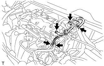
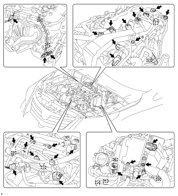
Attach the 10 clamps, and then connect the connectors.
-
Connect the engine wire with the 3 bolts and 2 nuts.
- Torque:
- for bolt A
- 8.4 N*m { 86 kgf*cm, 74 in.*lbf }
- for bolt B
- 10 N*m { 102 kgf*cm, 7 ft.*lbf }
- for nut
- 8.4 N*m { 86 kgf*cm, 74 in.*lbf }
-
-
INSTALL BATTERY TRAY
-
INSTALL BATTERY
-
INSTALL BATTERY CLAMP SUB-ASSEMBLY
-
Install the battery clamp with the bolt and nut.
- Torque:
- for bolt
- 17 N*m { 168 kgf*cm, 12 ft.*lbf }
- for nut
- 3.5 N*m { 36 kgf*cm, 31 in.*lbf }
-
Connect the cable to the positive (+) battery terminal.
- Torque:
- 5.4 N*m { 55 kgf*cm, 48 in.*lbf }
-
-
INSTALL AIR CLEANER CASE SUB-ASSEMBLY
-
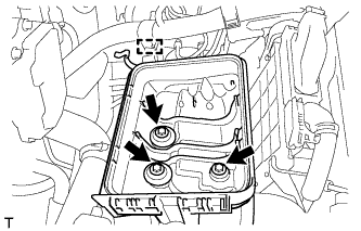
Install the air cleaner case with the 3 bolts.
- Torque:
- 7.0 N*m { 71 kgf*cm, 62 in.*lbf }
-
Attach the wire harness clamp to the air cleaner case.
-
-
INSTALL AIR CLEANER CAP SUB-ASSEMBLY
-
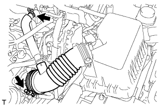
Connect the air cleaner cap with the band.
-
Connect the ventilation hose.
-
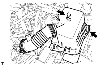
Connect the 2 clamps.
-
Attach the wire harness to the 2 clamps.
-
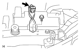
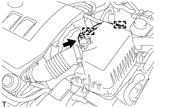
Connect the mass air flow meter connector.
-
-
CONNECT CABLE TO NEGATIVE BATTERY TERMINAL
Note
When disconnecting the cable, some systems need to be initialized after the cable is reconnected Click here.
-
INSTALL NO. 2 CYLINDER HEAD COVER
-
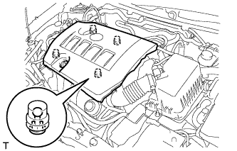
Attach the 4 clips to install the cover.
Note
-
Be sure to attach the clips securely.
-
Do not apply excessive force or hit the cover to attach the clips. This may cause the cover to break.
-
-
-
INSTALL RADIATOR SUPPORT OPENING COVER
-
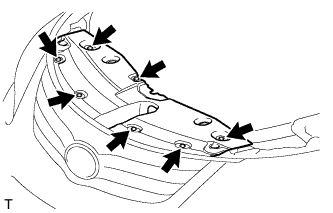
Install the radiator support opening cover with the 7 clips.
-