SFI SYSTEM DATA LIST / ACTIVE TEST

-
DATA LIST
Tech Tips
Using the intelligent tester to read the Data List allows the values or states of switches, sensors, actuators and other items to be read without removing any parts. This non-intrusive inspection can be very useful because intermittent conditions or singles may be discovered before parts or wiring is disturbed. Reading the Data List information early in troubleshooting is one way to save diagnostic time.
Note
In the table below, the values listed under Normal Condition are for reference only. Do not depend solely on these values when determining whether or not a part is faulty.
-
Warm up the engine.
-
Turn the ignition switch off.
-
Connect the intelligent tester to the DLC3.
-
Turn the ignition switch to ON and turn the tester on.
-
Enter the following menus: Powertrain / Engine and ECT / Data List.
-
Check the values by referring to the table below.
Tech Tips
If no idling conditions are specified, the transaxle should be in neutral, and the air conditioning switch and all accessory switches should be off.
Tester Display Measurement Item/Range Normal Condition Diagnostic Note Vehicle Speed Vehicle speed/
Min.: 0 km/h, Max.: 255 km/h
Actual vehicle speed The speed indicated on the speedometer. Engine Speed Engine speed/
Min.: 0 rpm, Max.: 16383 rpm
580 to 680 rpm: Idling - Calculate Load Load calculated by ECM/
Min.: 0%, Max.: 100%
-
10 to 30%: Idling
-
10 to 30%: Running without load (2500 rpm)
- Vehicle Load Vehicle load/
Min.: 0%, Max.: 25700%
Actual vehicle load - MAF Air flow rate from Mass Air Flow (MAF) meter/
Min.: 0 g/sec., Max.: 655.35 g/sec.
1 to 3 g/sec.: Idling If the value is approximately 0.0 g/sec.:
-
The Mass Air Flow (MAF) meter power source circuit is open.
-
VG circuit is open or shorted.
If the value is 160.0 g/sec. or more:
-
The E2G circuit is open.
Atmosphere Pressure Atmospheric pressure/
Min.: 0 kPa, Max.: 255 kPa
Equivalent to atmospheric pressure (absolute pressure) - MAP Intake manifold pressure/
Min.: 0 kPa, Max.: 255 kPa
90 to 105 kPa: Ignition switch ON - Coolant Temp Engine coolant temperature/
Min.: -40°C, Max.: 140°C
80 to 100°C (176 to 212°F): After warming up If the value is -40°C (-40°F), the sensor circuit is open.
If the value is 140°C (284°F), the sensor circuit is shorted.
Intake Air Intake air temperature/
Min.: -40°C, Max.: 140°C
Equivalent to ambient air temperature If the value is -40°C (-40°F), the sensor circuit is open.
If the value is 140°C (284°F), the sensor circuit is shorted.
Engine Run Time Engine run time/
Min.: 0 seconds, Max.: 65535 seconds
Time after engine start Service data. Initial Engine Coolant Temp Initial engine coolant temperature/
Min.: -40°C, Max.: 120°C
Close to ambient air temperature Service data. Initial Intake Air Temp Initial intake air temperature/
Min.: -40°C, Max.: 120°C
Close to ambient air temperature Service data. Battery Voltage Battery voltage/
Min.: 0 V, Max.: 65.5 V
11 to 14 V: Idling - Accel Sens. No. 1 Volt % Absolute Accelerator Pedal Position (APP) No. 1/
Min.: 0%, Max.: 100%
10 to 22%: accelerator pedal released
52 to 90%: accelerator pedal fully depressed
- Accel Sens. No. 2 Volt % Absolute APP No. 2/
Min.: 0%, Max.: 100%
24 to 40%: accelerator pedal released
68 to 100%: accelerator pedal fully depressed
- Accel Sensor Out No. 1 Accelerator pedal position sensor No. 1 voltage/
Min.: 0 V, Max.: 4.98 V
- ETCS freeze data. Accel Sensor Out No. 2 Accelerator pedal position sensor No. 2 voltage/
Min.: 0 V, Max.: 4.98 V
- ETCS freeze data. Accel Sensor Out No. 1 Accelerator pedal position sensor No. 1 voltage
Min.: 0 V, Max.: 4.9 V
0.5 to 1.1 V: accelerator pedal released
2.6 to 4.5 V: accelerator pedal fully depressed
Read value with ignition switch ON (Do not start engine) Accel Sensor Out No. 2 Accelerator pedal position sensor No. 2 voltage/
Min.: 0 V, Max.: 4.9 V
1.2 to 2.0 V: accelerator pedal released
3.4 to 5.0 V: accelerator pedal fully depressed
Read value with ignition switch ON (Do not start engine) Accelerator Idle Position Whether or not accelerator pedal position sensor detecting idle/
ON or OFF
ON: Idling - Accel Fully Close #1 (AD) Accelerator pedal position sensor No. 1 voltage (AD)/
Min.: 0 V, Max.: 4.9 V
- ETCS service data. Accel Fully Close Learn #1 Accelerator fully closed learned value No. 1/
Min.: 0 deg, Max.: 124.5 deg
- ETCS service data. Accel Fully Close Learn #2 Accelerator fully closed learned value No. 2/
Min.: 0 deg, Max.: 124.5 deg
- ETCS service data. Throttle Sensor Volt % Throttle sensor positioning/
Min.: 0%, Max.: 100%
-
10 to 22%: Throttle fully closed
-
64 to 96%: Throttle fully open
The calculated value based on VTA1. Throttl Sensor #2 Volt % Throttle position sensor #2/
Min.: 0%, Max.: 100%
-
42 to 62%: Throttle fully closed
-
92 to 100%: Throttle fully open
The calculated value based on VTA2. ST1 Brake pedal signal/
ON or OFF
ON: Brake pedal depressed - System Guard System guard/
ON or OFF
- ETCS service data. Open Side Malfunction Open side malfunction/
ON or OFF
- ETCS service data. Throttle Idle Position Whether or not throttle position sensor detecting idle/
ON or OFF
ON: Accelerator pedal released
OFF: Accelerator pedal depressed
- Throttle Require Position Throttle requirement position/
Min.: 0 V, Max.: 4.9 V
0.5 to 1.1 V: Idling - Throttle Sensor Position* Absolute throttle position sensor/
Min.: 0%, Max.: 100%
-
0%: Throttle fully closed
-
50 to 80%: Throttle fully open
Recognition value for throttle opening angle on ECM Throttle Position No. 1 Throttle position sensor No. 1 output voltage/
Min.: 0 V, Max.: 4.98 V
- ETCS freeze data. Throttle Position No. 2 Throttle position sensor No. 2 output voltage/
Min.: 0 V, Max.: 4.98 V
- ETCS freeze data. Throttle Position No. 1 Throttle position sensor No. 1 output voltage/
Min.: 0 V, Max.: 4.9 V
-
0.5 to 1.1 V: Throttle fully closed
-
3.2 to 4.8 V: Throttle fully open
-
0.6 to 1.4 V: Fail-safe
- Throttle Position No. 2 Throttle position sensor No. 2 output voltage/
Min.: 0 V, Max.: 4.9 V
-
2.1 to 3.1 V: Throttle fully closed
-
4.6 to 5.0 V: Throttle fully open
-
2.1 to 3.1 V: Fail-safe
- Throttle Position Command Throttle position command value/
Min.: 0 V, Max.: 4.9 V
0.5 to 4.8 V - Throttle Sens Open Pos #1 Throttle position sensor No. 1/
Min.: 0 V, Max.: 4.9 V
0.6 to 1.4 V ETCS service data. Throttle Sens Open Pos #2 Throttle position sensor No. 2/
Min.: 0 V, Max.: 4.9 V
1.7 to 2.5 V ETCS service data. Throttle Sens Open #1 (AD) Throttle position sensor No. 1 output voltage (AD)/
Min.: 0 V, Max.: 4.9 V
0.5 to 4.8 V - Throttle Motor Whether throttle actuator control permitted/
ON or OFF
-
ON: Ignition switch ON
-
OFF: ETCS has failed
- Throttle Motor Current Throttle actuator current/
Min.: 0 A, Max.: 19.9 A
0 to 3.0 A: Idling ETCS service data. Throttle Motor DUTY Throttle actuator/
Min.: 0%, Max.: 100%
10 to 22%: Idling after engine warmed up ETCS service data. Throttle Motor Current Throttle actuator current/
Min.: 0 A, Max.: 19.92 A
- ETCS service data. Throttle Motor Open Duty Throttle actuator open duty ratio/
Min.: 0%, Max.: 100%
- ETCS service data. Throttle Motor Close Duty Throttle actuator closed duty ratio/
Min.: 0%, Max.: 100%
- ETCS service data. Throttle Motor Duty (Open) Throttle actuator duty ratio (open)/
Min.: 0%, Max.: 100%
0 to 40%: Idling ETCS service data. Throttle Motor Duty (Close) Throttle actuator duty ratio (close)/
Min.: 0%, Max.: 100%
0 to 40%: Idling ETCS service data. Throttle Fully Close Learn Throttle valve fully closed (learned value)/
Min.: 0, Max.: 4.9 V
0.4 to 1.0 V: Accelerator pedal released - ETCS Actuator Power ETCS power supply/
ON or OFF
-
ON: Ignition switch ON and system normal
-
OFF: ETCS has failed
- +BM Voltage +BM voltage/
Min.: 0, Max.: 19.9
11 to 14 V: Ignition switch ON and system normal ETCS service data. Actuator Power Supply Actuator power supply/
ON or OFF
ON: Idling ETCS service data. Clutch Current Clutch current/
Min.: 0 A, Max.: 2.49 A
- ETCS service data. Fail Safe Drive Whether or not fail safe function executed/
ON or OFF
-
ON: ETCS has failed
-
OFF: ETCS normal
ETCS service data. Fail Safe Drive (Main CPU) Whether or not fail safe function executed/
ON or OFF
-
ON: ETCS has failed
-
OFF: ETCS normal
ETCS service data. Injector (Port) Injection period of the No. 1 cylinder/
Min.: 0 ms, Max.: 32.64 ms
1.0 to 3.0 ms: Idling - Injection Volum (Cylinder 1) Injection volume (cylinder 1)/
Min.: 0 ml, Max.: 2.048 ml
0.05 to 0.15 ml: Idling The quantity of fuel injection volume for 10 times. Fuel Pump/Speed Status Fuel pump/speed status/
ON or OFF
- The Active Test support data. EVAP (Purge) VSV Purge VSV control duty/
Min.: 0%, Max.: 100%
0 to 50%: Idling, under purge control The order signal from the ECM. Evap Purge Flow Purge flow/
Min.: 0%, Max.: 102.3%
0 to 10%: Idling - Purge Density Learn Value Learned value of purge density/
Min.: -50, Max.: 349.99
-40 to 0%: Idling Service data. EVAP Purge VSV VSV status for EVAP control/
ON or OFF
- The Active Test support data. Target Air-Fuel Ratio Air-fuel ratio/
Min.: 0, Max.: 1.998
0.8 to 1.2: During idling - AF Lambda B1 S1 Short-term fuel trim (for Bank 1 Sensor 1)/
Min.: 0, Max.: 1.99
-
Value less than 1 (0.000 to 0.999) = Rich
-
1 = Stoichiometric air-fuel ratio
-
Value more than 1 (1.001 to 1.999) = Lean
- AFS Voltage B1 S1 Air fuel ratio sensor output voltage (for Bank 1 Sensor 1)/
Min.: 0 V, Max.: 7.99 V
2.6 to 3.8 V: Idling Performing the Control the Injection Volume or Control the Injection Volume for A/F Sensor function of the Active Test enables the technician to check voltage output of the sensor. AFS Current B1 S1 Air fuel ratio sensor current (for Bank 1 Sensor 1)/
Min.: -128 mA, Max.: 127.99 mA
-0.5 to 0.5 mA: Idling Performing the Control the Injection Volume or Control the Injection Volume for A/F Sensor function of the Active Test enables the technician to check the output voltage of the sensor. O2S B1 S2 Heated oxygen sensor output voltage (for Bank 1 Sensor 2)/
Min.: 0 V, Max.: 1.27 V
0.0 to 0.9 V:
Vehicle driven at 70 km/h (44 mph)
Performing the Control the Injection Volume or Control the Injection Volume for A/F Sensor function of the Active Test enables the technician to check voltage output of the sensor. Short FT #1 Short-term fuel trim of bank 1/
Min.: -100%, Max.: 99.2%
-20 to +20% This item refers to the short-term fuel compensation used to maintain the air-fuel ratio at the stoichiometric air-fuel ratio. Long FT #1 Long-term fuel trim of bank 1/
Min.: -100%, Max.: 99.2%
-20 to +20% This item refers to the overall fuel compensation carried out in the long-term to compensate a continual deviation of the short-term fuel trim from the central value. Total FT #1 Total fuel trim of bank 1
Average value for fuel trim system of bank 1/
Min.: -0.5, Max.: 0.496
-0.28 to 0.2: Idling - Fuel System Status #1 Fuel system status (Bank 1)/
OL, CL, OL Drive, OL Fault or CL Fault
CL: Idling after warming up
-
OL (Open Loop): Has not yet satisfied the conditions to go to closed loop.
-
CL (Closed Loop): Using the heated oxygen sensor as feedback for fuel control.
-
OL Drive: Open loop due to driving conditions (fuel enrichment).
-
OL Fault: Open loop due to a detected system fault.
-
CL Fault: Closed loop but the heated oxygen sensor, which is used for fuel control, is malfunctioning.
Fuel System Status #2 Fuel system status (Bank 2)/
OL, CL, OL Drive, OL Fault or CL Fault
Unused
-
OL (Open Loop): Has not yet satisfied the conditions to go to closed loop.
-
CL (Closed Loop): Using the heated oxygen sensor as feedback for fuel control.
-
OL Drive: Open loop due to driving conditions (fuel enrichment).
-
OL Fault: Open loop due to a detected system fault.
-
CL Fault: Closed loop but the heated oxygen sensor, which is used for fuel control, is malfunctioning.
IGN Advance Ignition timing advance for No. 1 cylinder/
Min.: -64 deg., Max.: 63.5 deg.
BTDC 0 to 15°: Idling - Knock Feedback Value Feedback value of knocking/
Min.: -64° CA, Max.: 1983.9° CA
-20 to 0° CA:
Vehicle driven at 70 km/h (44 mph)
Service data. Knock Correct Learn Value Correction learned value of knocking/
Min.: -64° CA, Max.: 1983.9° CA
0 to 20° CA:
Vehicle driven at 70 km/h (44 mph)
Service data. ACIS VSV VSV status for ACIS control/
ON or OFF
- The Active Test support data. VVT Control Status #1 Variable valve timing (VVT) control status (Bank 1)/
ON or OFF
- The Active Test support data. VVT Aim Angle #1 VVT aim angle (Bank 1)/
Min.: 0%, Max.: 100%
0 to 100% VVT duty signal value during forced operation. VVT Change Angle #1 VVT change angle (Bank 1)/
Min.: 0° FR, Max.: 60° FR
0 to 55° FR: Idling Displacement angle during forced operation. VVT OCV Duty #1 VVT OCV operation duty (Bank 1)/
Min.: 0%, Max.: 100%
0 to 100% Requested duty value for forced operation. VVT Ex Hold Lrn Val #1 VVT exhaust hold duty ratio learned value (Bank 1)/
Min.: 0%, Max.: 100%
0 to 80%: Idling - VVT Ex Chg Angle #1 VVT exhaust change angle (for Bank 1)/
Min.: 0° FR, Max.: 60° FR
0 to 45° FR: Idling Displacement angle during forced operation. VVT Ex OCV Duty #1 VVT exhaust OCV duty (for Bank 1)/
Min.: 0%, Max.: 100%
0 to 100%: Idling Requested duty value for forced operation. VALVEMATIC Target Angle VALVEMATIC target duration/
Min.: 90° CA, Max.: 260° CA
"High" selected in "Activate the VALVEMATIC (ENG ON)" Active Test: 260°CA
"Low" selected in "Activate the VALVEMATIC (ENG ON)" Active Test: 106°CA
Valid display is shown only when the Active Test is performed. VALVEMATIC Current Angle Actual VALVEMATIC duration/
Min.: 90° CA, Max.: 260° CA
"High" selected in "Activate the VALVEMATIC (ENG ON)" Active Test: 260°CA
"Low" selected in "Activate the VALVEMATIC (ENG ON)" Active Test: 106°CA
Minimum duration: 106° CA
Maximum duration: 260° CA
VALVEMATIC IG OFF VALVEMATIC operation state
ON or OFF
ON: Operating with ignition switch off
Cannot check with intelligent tester when ignition switch off
One of the items in this Data List, which shows the operating state of the VALVEMATIC, is ON. VALVEMATIC IG ON VALVEMATIC operation state
ON or OFF
ON: Ignition switch ON and engine not running VALVEMATIC Cranking VALVEMATIC operation state
ON or OFF
ON: While starting engine (during cranking) VALVEMATIC bef Warm Up VALVEMATIC operation state
ON or OFF
ON: Engine running before engine warmed up (engine coolant temperature 60°C (140°F) or less) or during "Activate the VALVEMATIC before Warm Up" Active Test VALVEMATIC aft Warm Up VALVEMATIC operation state
ON or OFF
ON: Engine running after engine warmed up (engine coolant temperature 60°C (140°F) or higher) or during "Activate the VALVEMATIC after Warm Up" Active Test VALVEMATIC IDM Hi Temp VALVEMATIC operation state
ON or OFF
ON: Continuously variable valve lift controller assembly overheating VALVEMATIC Low (ACT) VALVEMATIC operation state
ON or OFF
ON: System operating with minimum valve lift or "Low" selected in "Activate the VALVEMATIC (ENG ON)" Active Test VALVEMATIC High (ACT) VALVEMATIC operation state
ON or OFF
ON: System operating with maximum valve lift or "High" selected in "Activate the VALVEMATIC (ENG ON)" Active Test Catalyst Temp B1 S1 Catalyst temperature (for Bank 1 Sensor 1)/
Min.: -40°C, Max.: 6513.5°C
- - Catalyst Temp B1 S2 Catalyst temperature (for Bank 1 Sensor 2)/
Min.: -40°C, Max.: 6513.5°C
- - Starter Signal Starter signal/
ON or OFF
ON: Cranking - Power Steering Signal Record Power steering switch signal/
ON or OFF
- - Power Steer. Sig. Record Power steering signal (history)/
ON or OFF
ON: When steering wheel first turned after battery terminals connected Signal status usually ON until battery terminals disconnected Clutch Switch Clutch switch/
ON or OFF
ON: Clutch pedal depressed - Reverse Switch Reverse switch/
ON or OFF
ON: Shift position in R - Stop Light Switch Stop light switch/
ON or OFF
ON: Brake pedal depressed - Shift Indication Enable Shift indication enable/
ON or OFF
- - A/C Signal A/C switch status/
ON or OFF
ON: A/C ON - Closed Throttle Position SW Closed throttle position switch/
ON or OFF
-
ON: Throttle fully closed
-
OFF: Throttle open
- Fuel Cut Condition Fuel cut condition/
ON or OFF
ON: Fuel cut operating - Immobiliser Communication Immobiliser communication/
ON or OFF
ON: Normal - Electrical Load Signal Electrical load signal/
ON or OFF
ON: Headlights or defogger turned ON - Check Mode Check mode/
ON or OFF
ON: Check mode ON Refer to Check Mode Procedure Click here.
SPD Test Result Check mode result for vehicle speed sensor/
Compl or Incmpl
- - Misfire Test Result Check mode result for misfire monitor/
Compl or Incmpl
- - OXS1 Test Result Check mode result for heated oxygen sensor (Bank 1)/
Compl or Incmpl
- - A/F Test Results #1 Check mode result for air-fuel ratio sensor/
Compl or Incmpl
- - Complete Parts Monitor Comprehensive component monitor/
Not Avl or Avail
- - Fuel System Monitor Fuel system monitor/
Not Avl or Avail
- - Misfire Monitor Misfire monitor/
Not Avl or Avail
- - EGR/VVT Monitor EGR/VVT monitor/
Not Avl or Avail
- - EGR/VVT Monitor EGR/VVT monitor/
Compl or Incmpl
- - O2S(A/FS) Heater Monitor O2S (A/FS) heater monitor/
Not Avl or Avail
- - O2S(A/FS) Heater Monitor O2S (A/FS) heater monitor/
Compl or Incmpl
- - O2S(A/FS) Monitor O2S (A/FS) monitor/
Not Avl or Avail
- - O2S(A/FS) Monitor O2S (A/FS) monitor/
Compl or Incmpl
- - A/C Monitor A/C monitor/
Not Avl or Avail
- - A/C Monitor A/C monitor/
Compl or Incmpl
- - 2nd Air Monitor 2nd air monitor/
Not Avl or Avail
- - 2nd Air Monitor 2nd air monitor/
Compl or Incmpl
- - EVAP Monitor EVAP monitor/
Not Avl or Avail
- - EVAP Monitor EVAP monitor/
Compl or Incmpl
- - Heated Catalyst Monitor Heated catalyst monitor/
Not Avl or Avail
- - Heated Catalyst Monitor Heated catalyst monitor/
Compl or Incmpl
- - Catalyst Monitor Catalyst monitor/
Not Avl or Avail
- - Catalyst Monitor Catalyst monitor/
Compl or Incmpl
- - # Codes (Include History) Number of codes/
Min.: 0, Max.: 255
- The number of stored DTCs. MIL MIL status/
ON or OFF
ON: MIL on - MIL ON Run Distance MIL on run distance/
Min.: 0 km, Max.: 65535 km
Distance after DTC stored - Running Time from MIL ON Running time from MIL on/
Min.: 0 minutes, Max.: 65535 minutes
Equivalent to running time after MIL on - Time after DTC Cleared Time after DTC cleared/
Min.: 0 minutes, Max.: 65535 minutes
Equivalent to time after DTCs cleared - Distance from DTC Cleared Distance after DTC cleared/
Min.: 0 km, Max.: 65535 km
Equivalent to driven distance after DTCs cleared - Warmup Cycle Cleared DTC Warm-up cycle after DTC cleared/
Min.: 0, Max.: 255
- The number of warm-up cycles after the DTC is cleared. OBD Requirements OBD requirement E-OBD - Number of Emission DTC Emission-related DTCs - The number of emission-related DTCs. TC and TE1 TC and TE1 terminal of DLC3/
ON or OFF
- - Ignition Trig. Count Ignition counter/
Min.: 0, Max.: 800
0 to 800 - Cylinder #1 Misfire Count
to
Cylinder #4 Misfire Count
Misfire counter of cylinder 1 to 4/
Min.: 0, Max.: 255
0 to 16 - All Cylinders Misfire Count All cylinders misfire counter/
Min.: 0, Max.: 255
0 to 16 - Misfire RPM Engine speed for first misfire range/
Min.: 0 rpm, Max.: 6375 rpm
0 rpm: Misfire 0 - Misfire Load Engine load for first misfire range/
Min.: 0 g/rev, Max.: 3.98 g/rev
0 g/rev: Misfire 0 - Misfire Margin Misfire monitoring/
Min.: -100%, Max.: 99.21%
-100 to 99.2% The misfire detecting margin. Electric Fan Motor Electric fan motor status/
ON or OFF
- - Idle Fuel Cut Fuel cut idle/
ON or OFF
ON: Fuel cut operation Idle Fuel Cut is "ON" when the throttle valve is fully closed and the engine speed is more than 2800 rpm. FC TAU Fuel cut TAU: Fuel cut during very light load/
ON or OFF
ON: Fuel cut operation The fuel cut being performed under a very light load to prevent the engine combustion from becoming incomplete. Model Code Model code - The identifying model code:
ZRT270#
Engine Type Engine type - The identifying engine type:
1ZRFAE
Cylinder Number Number of cylinders/
Min.: 0, Max.: 255
- The identifying number of cylinders:
4
Transmission Type Transaxle type - The identifying transaxle type:
MT
Destination Destination - The identifying destination:
W
Model Year Model year/
Min.: 1900, Max.: 2155
- The identifying model year:
20##
System Identification System identification - The identifying engine system:
Gasoline (gasoline engine)
Engine Speed of Cyl #1 Engine speed for cylinder 1/
Min.: 0 rpm, Max.: 25600 rpm
- Output only when Check the Cylinder Compression is performed using the Active Test. Engine Speed of Cyl #2 Engine speed for cylinder 2/
Min.: 0 rpm, Max.: 25600 rpm
- Output only when Check the Cylinder Compression is performed using the Active Test. Engine Speed of Cyl #3 Engine speed for cylinder 3/
Min.: 0 rpm, Max.: 25600 rpm
- Output only when Check the Cylinder Compression is performed using the Active Test. Engine Speed of Cyl #4 Engine speed for cylinder 4/
Min.: 0 rpm, Max.: 25600 rpm
- Output only when Check the Cylinder Compression is performed using the Active Test. Av Engine Speed of All Cyl Engine speed for all cylinders/
Min.: 0 rpm, Max.: 25600 rpm
- Output only when Check the Cylinder Compression is performed using the Active Test. MT Down Shift Indication MT down shift indication/
ON or OFF
- - MT Up Shift Indication MT up shift indication/
ON or OFF
- -
-
*: Excluding throttle valve opening percentage due to Idle Speed Control (ISC).
-
-
ACTIVE TEST
Tech Tips
Using the intelligent tester to perform Active Tests allows relays, VSVs, actuators and other items to be operated without removing any parts. This non-intrusive functional inspection can be very useful because intermittent operation may be discovered before parts or wiring is disturbed. Performing Active Tests early in troubleshooting is one way to save diagnostic time. Data List information can be displayed while performing Active Tests.
-
Data List can be displayed during Active Tests.
-
Connect the intelligent tester to the DLC3.
-
Turn the ignition switch to ON and turn the tester on.
-
Enter the following menus: Powertrain / Engine and ECT / Active Test.
-
Perform Active Tests by referring to the table below.
Tester Display Test Part Control Range Diagnostic Note Control the Injection Volume Change injection volume -12.5 to 24.8%
-
All the injectors are tested at the same time.
-
Perform the test at less than 3000 rpm.
-
The injection volume can be changed in 0.2% graduations within the control range.
Control the Injection Volume for A/F Sensor Change injection volume Lower by -12.5% or increase by 25%
-
Perform the test at less than 3000 rpm.
-
Control the Injection Volume for A/F Sensor enables the checking and graphing of the A/F (Air Fuel Ratio) sensor and Heated Oxygen (HO2) sensor voltage outputs.
-
To conduct the test, enter the following menus: Active Test / Control the Injection Volume for A/F Sensor / Data List / A/F Control System / AFS Voltage B1 S1 and O2S B1 S2.
Activate the VSV for Intake Control Activate VSV for intake control ON/OFF - Activate the VSV for Evap Control Activate purge VSV control ON/OFF - Control the Fuel Pump / Speed Activate fuel pump (C/OPN Relay) ON/OFF The test is possible when the following conditions are met:
-
The ignition switch is ON.
-
The engine is stopped.
Connect the TC and TE1 Turn on and off TC and CG (TE1) connection ON/OFF
-
ON: TC and TE1 are connected.
-
OFF: TC and TE1 are disconnected.
Control the Idle Fuel Cut Prohibit Prohibit idling fuel cut control ON/OFF The idling fuel-cut is turned ON when the throttle valve is fully closed and the engine speed is more than 2800 rpm. Control the Electric Cooling Fan Control electric cooling fan motor ON/OFF - Control the ETCS Open/Close Slow Speed Throttle actuator Close/Open The test is possible when the following conditions are met:
-
The ignition switch is ON.
-
The engine is stopped.
-
The accelerator pedal is fully depressed (APP: 58 degrees or more).
Control the ETCS Open/Close Fast Speed Throttle actuator Close/Open Control the VVT Linear (Bank1) Control VVT (Bank 1) Between -128 and 127%
-
The engine stalls or idles roughly when the VVT actuator is operated at 100%.
-
The test is possible during idle.
Control the VVT System (Bank1) Turn on and off OCV
(Camshaft Timing Oil Control Valve)
ON/OFF
-
The engine stalls or idles roughly when the OCV is turned ON.
-
The engine is running and idles normally when the OCV is OFF.
-
The test is possible during idle.
Control the VVT Exhaust Linear (Bank 1) Control VVT (Bank 1) Between -128 and 127%
-
The engine stalls or idles roughly when the VVT actuator is operated at 100%.
-
The test is possible during idle.
Control the Cylinder #1 Fuel Cut Cylinder #1 injector fuel cut ON/OFF The test is possible while the vehicle is stopped and the engine is idling. Control the Cylinder #2 Fuel Cut Cylinder #2 injector fuel cut ON/OFF Control the Cylinder #3 Fuel Cut Cylinder #3 injector fuel cut ON/OFF Control the Cylinder #4 Fuel Cut Cylinder #4 injector fuel cut ON/OFF Control the All Cylinders Fuel Cut All cylinder fuel cut ON/OFF Check the Cylinder Compression *3 Check the cylinder compression pressure
(measuring engine speed for each cylinder)
ON/OFF Fuel injection and ignition stop in all the cylinders. Activate the VALVEMATIC (ENG OFF)*1 Moves continuously variable valve lift controller assembly to position corresponding to minimum or maximum duration High/Low
-
The engine is not running.
-
The ignition switch is ON
-
The continuously variable valve lift controller assembly is removed from the engine.
-
The engine coolant temperature is 0°C (32°F) or higher.
Activate the VALVEMATIC (ENG ON)*2 Operates VALVEMATIC system to set valve lift to maximum or minimum High/Low
-
The vehicle is stationary.
-
The engine coolant temperature is 40°C (104°F) or higher.
-
The shift lever is in neutral.
-
The vehicle should not be driven.
Activate the VALVEMATIC before Warm Up Sets VALVEMATIC system to operating position that occurs before engine warmed up ON/OFF
-
The vehicle is stationary.
-
The engine is not running.
-
The engine coolant temperature is 40°C (104°F) or higher.
-
The shift lever is in neutral.
-
After the Active Test is performed, driving the vehicle is possible
Activate the VALVEMATIC after Warm Up Sets VALVEMATIC system to operating position that occurs after engine warmed up ON/OFF
-
The vehicle is stationary.
-
The engine is not running.
-
The engine coolant temperature is 40°C (104°F) or higher.
-
The shift lever is in neutral.
-
After the Active Test is performed, driving the vehicle is possible
Tech Tips
-
*1: If the engine is cranked for 5 seconds or more while power to the ECM and continuously variable valve lift controller assembly is cut, perform the "Activate the VALVEMATIC (ENG OFF)" Active Test by selecting "Low". By performing this procedure, the minimum valve lift value for the "continuously variable valve lift controller assembly" can be learned.
-
*2: Maintain an engine speed of 3000 rpm with the shift lever in neutral, and if the MAP changes when the value of the "Activate the VALVEMATIC (ENG ON)" Active Test is changed between "Low" and "High", the VALVEMATIC system is normal.
Result High VALVEMATIC Current Angle: 260°CA, MAP: 20 to 35 kPa (150 to 263 mmHg, 5.91 to 10.3 in.Hg) Low VALVEMATIC Current Angle: 106°CA, MAP: 70 to 100 kPa (525 to 750 mmHg, 20.7 to 29.5 in.Hg) -
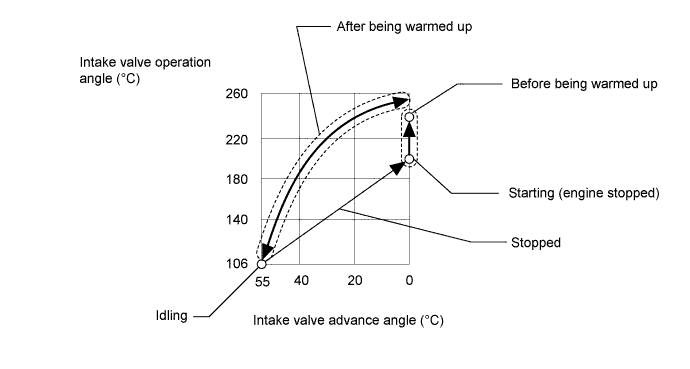
Refer to the illustration for the intake valve duration, state of VVT operation and VALVEMATIC operation position before and after warming up the engine.
-
*3: When performing the Active Test item "Check the Cylinder Compression" and then cranking the engine, the ECM stops the fuel injection and ignition, and measures the engine speed for each cylinder.
If the speed of one cylinder is higher than the others, the compression pressure of that cylinder can be concluded to be less than the others.
-
Warm up the engine.
-
Turn the ignition switch off.
-
Connect the intelligent tester to the DLC3.
-
Turn the ignition switch to ON.
-
Turn the intelligent tester on.
-
Enter the following menus: Powertrain / Engine and ECT / Active Test / Check the Cylinder Compression.
-
Select the following monitor items: Compression / Engine Speed of Cyl #1 to Engine Speed of Cyl #4, Av Engine Speed of All Cyl.
-
Press the RIGHT or LEFT button to change Check the Cylinder Compression to on.
Tech Tips
Fuel injection and ignition for all the cylinders are prohibited at this time, and the engine speed measurement of each cylinder will enter standby mode.
-
Crank the engine until the monitor item values "Engine speed of Cyl #1 to Engine Speed of Cyl #4" and "Av Engine Speed of All Cyl" change.
-
Monitor the engine speed (Engine Speed of Cyl #1 to Engine Speed of Cyl #4, Av Engine Speed of All Cyl) displayed on the intelligent tester.
Tech Tips
The intelligent tester displays extremely high values before cranking the engine. The engine speed of each cylinder is measured while cranking the engine and then the intelligent tester displays the actual engine speed values.
Note
-
The Active Test item "Check the Cylinder Compression" will automatically turn off 255 seconds after the Active Test is turned on.
-
When the "Check the Cylinder Compression" is OFF and the engine is cranked, the engine will start.
-
If the "Check the Cylinder Compression" test needs to be performed again after the engine speed measurement of each cylinder has been performed once, press EXIT to return to the Active Test menu screen. Then perform the Check the Cylinder Compression test again.
-
Use a fully-charged battery.
-
-