SFI SYSTEM Variable Resistor Circuit
DESCRIPTION
The variable resistor is used to adjust the concentration of CO in the exhaust during idling. By turning the idle mixture adjusting screw located on the variable resistor clockwise, the contact inside the resistor is moved and the voltage at the VAF terminal rises accordingly. Conversely, turning the adjusting screw counterclockwise reduces the VAF terminal voltage. When the VAF terminal voltage rises, the ECM increases the fuel injection volume slightly, thus making the air-fuel ratio slightly richer.
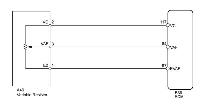
WIRING DIAGRAM
INSPECTION PROCEDURE
Note
Always use a CO meter when adjusting the concentration of CO during idling. If a CO meter is not available, do not attempt to adjust the idling CO concentration.
PROCEDURE
-
CHECK CO/HC
-
Make sure the following conditions are met:
-
All the vacuum lines are properly connected.
-
The CO meter is properly calibrated.
-
-
Start the engine.
-
Make sure the following conditions are met:
-
The parking brake is securely applied.
-
The shift lever is in P.
-
All the accessories are switched off.
-
-
Warm up the engine and check that the idling speed is appropriate.
-
Race the engine at 2500 rpm for approximately 3 minutes.
-
Insert a tester probe at least 40 cm (1.3 ft) into the tailpipe.
-
Measure the CO concentration 1 to 3 minutes after racing the engine to allow the concentration to stabilize.
Standard CO concentration rate at idling 1.0 to 2.0% Tech Tips
If the result is outside the standard range shown above, maintain the measurement conditions established during this procedure. The measurement conditions are used in the CO concentration adjustment procedure described below.
NG 
ADJUST CO CONCENTRATION Click here
OK 
PROCEED TO NEXT SUSPECTED AREA SHOWN IN PROBLEM SYMPTOMS TABLE Click here
-
-
ADJUST CO CONCENTRATION
-
Make sure that all the conditions established in the previous procedure remain unchanged.
-
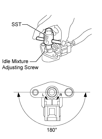
Regulate the idling CO concentration so that it is within 1.0 to 2.0%.
Tech Tips
Use SST and the idle mixture adjusting screw located on the A49 variable resistor. By turning the adjusting screw, the idling CO concentration rate can be regulated.
Reference Result Proceed To Unable to obtain standard concentration rate A Standard concentration rate obtained B - SST
- 09243-00020
B 
ADJUSTMENT COMPLETE
A 
-
-
INSPECT VARIABLE RESISTOR
-
Remove the variable resistor.
-
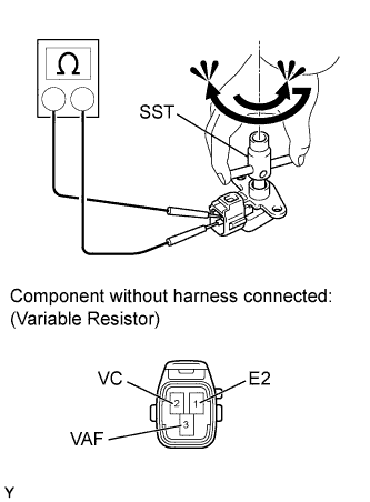
Measure the resistance according to the value(s) in the table below.
Standard Resistance Tester Connection Condition Specified Condition 1 (E2) - 2 (VC) Always 3.5 to 6.5 kΩ -
Measure the resistance according to the value(s) in the table below.
Standard Resistance Tester Connection Condition Specified Condition 1 (E2) - 3 (VAF) Adjusting screw turned fully clockwise 3.5 to 6.5 kΩ Adjusting screw turned fully counterclockwise 0 kΩ - SST
- 09243-00020
Tech Tips
When the adjusting screw is turned fully clockwise, the resistance is the same as the measurement value between terminals 1 and 2. When the adjusting screw is turned fully counterclockwise, the resistance changes to 0 kΩ.
-
Reinstall the variable resistor.
NG
REPLACE VARIABLE RESISTOR
OK
-
-
CHECK HARNESS AND CONNECTOR (VARIABLE RESISTOR - ECM)
-
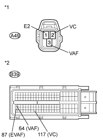
Text in Illustration *1 Front view of wire harness connector
(to Variable Resistor)
*2 Front view of wire harness connector
(to ECM)
Disconnect the A49 variable resistor connector.
-
Disconnect the B39 ECM connector.
-
Measure the resistance according to the value(s) in the table below.
Standard Resistance (Check for Open) Tester Connection Condition Specified Condition A49-2 (VC) - B39-117 (VC) Always Below 1 Ω A49-3 (VAF) - B39-64 (VAF) A49-1 (E2) - B39-87 (EVAF) Standard Resistance (Check for Short) Tester Connection Condition Specified Condition A49-2 (VC) or B39-117 (VC) - Body ground Always 10 kΩ or higher A49-3 (VAF) or B39-64 (VAF) - Body ground A49-1 (E2) or B39-87 (EVAF) - Body ground -
Reconnect the ECM connector.
-
Reconnect the variable resistor connector.
NG
REPAIR OR REPLACE HARNESS OR CONNECTOR (VARIABLE RESISTOR - ECM)
OK
-
-
INSPECT ECM (VC VOLTAGE)
-
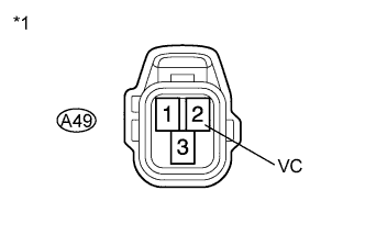
Text in Illustration *1 Front view of wire harness connector
(to Variable Resistor)
Disconnect the A49 variable resistor connector.
-
Measure the voltage according to the value(s) in the table below.
Standard Voltage Tester Connection Switch Condition Specified Condition A49-2 (VC) - Body ground Engine switch on (IG) 4.5 to 5.5 V -
Reconnect the variable resistor connector.
NG
REPLACE ECM Click here
OK
CHECK FOR INTERMITTENT PROBLEMS Click here
-