SFI SYSTEM, Diagnostic DTC:P0335, P0339

| DTC Code | DTC Name |
|---|---|
| P0335 | Crankshaft Position Sensor "A" Circuit |
| P0339 | Crankshaft Position Sensor "A" Circuit Intermittent |
DESCRIPTION
The Crankshaft Position (CKP) sensor system consists of a CKP sensor plate and a pickup coil. The sensor plate has 34 teeth and is installed on the crankshaft. The pickup coil is made of wound copper wire, an iron core and magnet.
The sensor plate rotates and, as each tooth passes by the pickup coil, a pulse signal is created. The pickup coil generates 34 signals per crankshaft revolution. Based on these signals, the ECM calculates the crankshaft position and engine speed. Using these calculations, the fuel injection time and ignition timing are controlled.
| DTC No. | DTC Detection Condition | Trouble Area |
|---|---|---|
| P0335 | Either condition is met:
|
|
| P0339 | Under conditions (a), (b) and (c), no CKP sensor signal is sent to the ECM for 0.05 seconds or more (1 trip detection logic): (a) The engine speed is 1000 rpm or more. (b) The starter signal is OFF. (c) 3 seconds or more have elapsed since the starter signal switched from ON to OFF. |
|
-
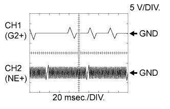
Reference: Inspection using an oscilloscope.
Tech Tips
-
The correct waveform is as shown.
-
G2+ stands for the CMP sensor signal, and NE+ stands for the CKP sensor signal.
-
Grounding failure of the shielded wire may cause noise in the waveforms.
Item Content Terminal CH1: G2+ - G2-
CH2: NE+ - NE-
Equipment Setting 5 V/DIV.
20 msec./DIV.
Condition Cranking or idling -
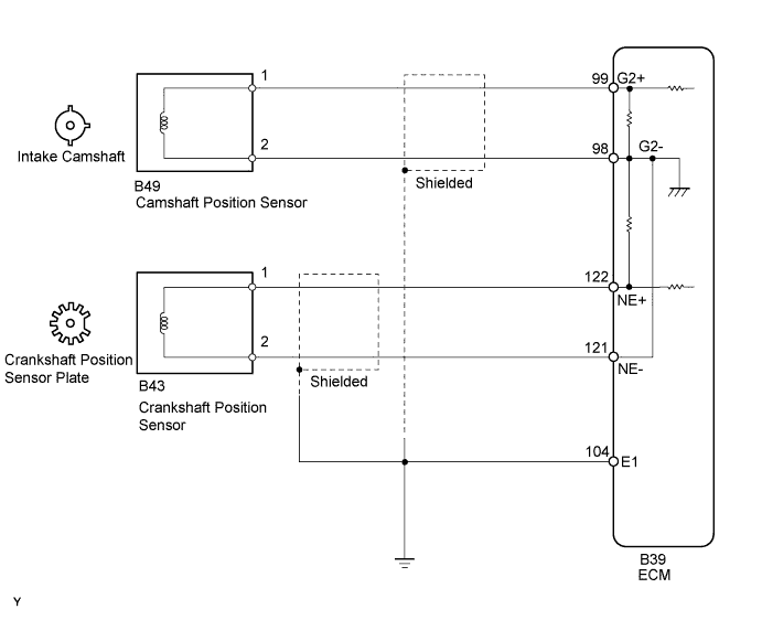
WIRING DIAGRAM
INSPECTION PROCEDURE
Tech Tips
-
If no problem is found through this diagnostic troubleshooting procedure, troubleshoot the engine mechanical system.
-
Check the engine speed. The engine speed can be checked by using the intelligent tester. To check, follow the operation below:
-
Connect the intelligent tester to the DLC3.
-
Start the engine.
-
Turn the tester on.
-
Enter the following menus: Powertrain / Engine and ECT / Data List / Engine Speed.
-
The engine speed may be indicated as zero despite the crankshaft revolving normally. This is caused by a lack of NE signals from the crankshaft position (CKP) sensor. Alternatively, the engine speed may be indicated as lower than the actual engine speed if the CKP sensor output voltage is insufficient.
-
Read freeze frame data using the intelligent tester. Freeze frame data records the engine conditions when malfunctions are detected. When troubleshooting, freeze frame data can help determine if the vehicle was moving or stationary, if the engine was warmed up or not, and other data from the time the malfunction occurred.
PROCEDURE
-
READ VALUE USING INTELLIGENT TESTER (ENGINE SPEED)
-
Connect the intelligent tester to the DLC3.
-
Turn the engine switch on (IG).
-
Turn the tester on.
-
Enter the following menus: Powertrain / Engine and ECT / Data List / Engine Speed.
-
Start the engine.
-
Read the values displayed on the tester while the engine is running.
OK Correct values are displayed. Tech Tips
-
To check the engine speed change, display the graph on the tester.
-
If the engine does not start, check the engine speed while cranking.
-
If the engine speed indicated on the tester remains at zero (0), there may be an open or short in the crankshaft position sensor circuit.
-
NG 
INSPECT CRANKSHAFT POSITION SENSOR (RESISTANCE) Click here
OK 
CHECK FOR INTERMITTENT PROBLEMS Click here
-
-
INSPECT CRANKSHAFT POSITION SENSOR (RESISTANCE)
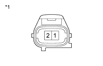
Text in Illustration *1 Component without harness connected
(Crankshaft Position Sensor)
-
Disconnect the B43 Crankshaft Position (CKP) sensor connector.
-
Measure the resistance according to the value(s) in the table below.
Standard Resistance Tester Connection Condition Specified Condition 1 - 2 Cold 985 to 1600 Ω 1 - 2 Hot 1265 to 1890 Ω Tech Tips
The terms cold and hot refer to the temperature of the sensor. Cold means approximately -10 to 50°C (14 to 122°F). Hot means approximately 50 to 100°C (122 to 212°F).
-
Reconnect the CKP sensor connector.
NG 
REPLACE CRANKSHAFT POSITION SENSOR Click here
OK 
-
-
CHECK HARNESS AND CONNECTOR (CRANKSHAFT POSITION SENSOR - ECM)
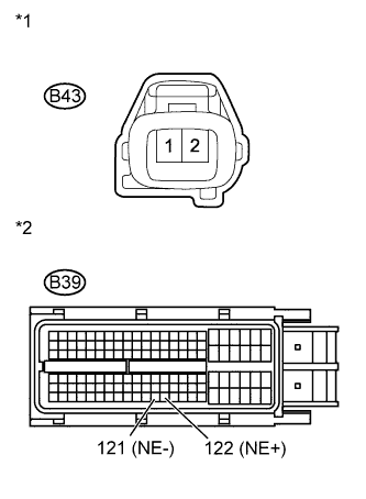
Text in Illustration *1 Front view of wire harness connector
(to Crankshaft Position Sensor)
*2 Front view of wire harness connector
(to ECM)
-
Disconnect the B43 CKP sensor connector.
-
Disconnect the B39 ECM connector.
-
Measure the resistance according to the value(s) in the table below.
Standard Resistance (Check for Open) Tester Connection Condition Specified Condition B43-1 - B39-122 (NE+) Always Below 1 Ω B43-2 - B39-121 (NE-) Standard Resistance (Check for Short) Tester Connection Condition Specified Condition B43-1 or B39-122 (NE+) - Body ground Always 10 kΩ or higher B43-2 or B39-121 (NE-) - Body ground -
Reconnect the ECM connector.
-
Reconnect the CKP sensor connector.
NG
REPAIR OR REPLACE HARNESS OR CONNECTOR
OK
-
-
CHECK SENSOR INSTALLATION (CRANKSHAFT POSITION SENSOR)
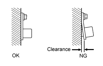
-
Check the CKP sensor installation.
OK Sensor is installed correctly.
NG
SECURELY REINSTALL CRANKSHAFT POSITION SENSOR Click here
OK
-
-
CHECK CRANKSHAFT POSITION SENSOR PLATE (TEETH OF SENSOR PLATE)
-
Check the teeth of the sensor plate.
OK Sensor plate teeth do not have any cracks or deformation.
NG
REPLACE CRANKSHAFT POSITION SENSOR PLATE Click here
OK
-
-
REPLACE CRANKSHAFT POSITION SENSOR
-
Replace the crankshaft position sensor Click here.
NEXT
-
-
CHECK WHETHER DTC OUTPUT RECURS
-
Connect the intelligent tester to the DLC3.
-
Turn the engine switch on (IG) and turn the tester on.
-
Clear DTCs Click here.
-
Start the engine.
-
Enter the following menus: Powertrain / Engine and ECT / DTC.
-
Read DTCs.
Result Result Proceed to No DTC output A DTC P0335 or P0339 output B Tech Tips
If the engine does not start, replace the ECM.
B
REPLACE ECM Click here
A
END
-