ENGINE UNIT REASSEMBLY

-
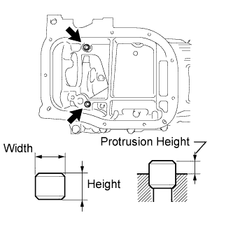
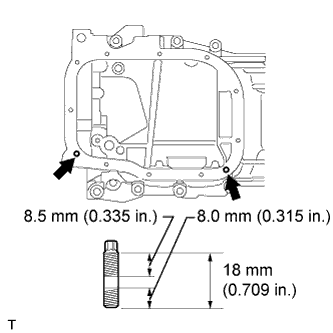
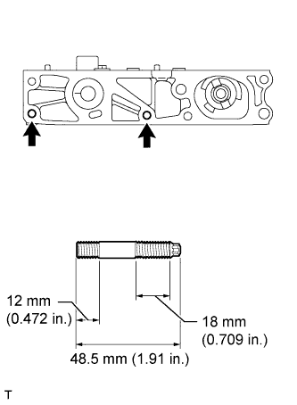
INSTALL STIFFENING CRANKCASE RING PIN
Note
It is not necessary to remove a ring pin unless it is being replaced.
-
Using a plastic-faced hammer, tap in 2 new ring pins until they stop.
Standard Ring Pin Item Protrusion Height Height Width Ring pin 3.0 mm (0.118 in.) 11 mm (0.433 in.) 8 mm (0.315 in.)
-
-
INSTALL STIFFENING CRANKCASE STUD BOLT
Note
If a stud bolt is deformed or the threads are damaged, replace it.
-
Using an E6 "TORX" socket wrench, install the stud bolts as shown in the illustration.
- Torque:
- 5.0 N*m { 51 kgf*cm, 44 in.*lbf }
-
-
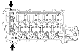
INSTALL STIFFENING CRANKCASE ASSEMBLY
-
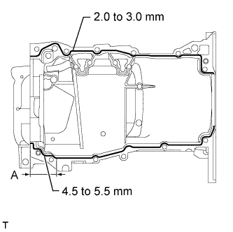
Apply seal packing in a continuous line as shown in the illustration.
Seal packing Toyota Genuine Seal Packing Black, Three bond 1207B or equivalent Standard Seal Diameter Area Specified Condition Continuous Line 2.0 to 3.0 mm (0.0787 to 0.118 in.) A 4.5 to 5.5 mm (0.177 to 0.217 in.) Application Length A 56 mm (2.20 in.) Note
-
Remove any oil from the contact surfaces.
-
Install the crankcase within 3 minutes and tighten the bolts within 15 minutes after applying seal packing.
-
Do not start the engine for at least 2 hours after installing the stiffening crankcase assembly.
-
-
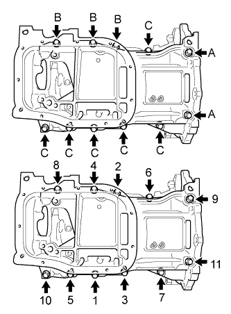
Install the stiffening crankcase with the 11 bolts in the sequence shown in the illustration.
- Torque:
- 21 N*m { 214 kgf*cm, 15 ft.*lbf }
Bolt Length Item Specified Condition Bolt A 138 mm (5.43 in.) Bolt B 35 mm (1.38 in.) Bolt C 70 mm (2.76 in.) -
Recheck the torque for bolts 1 and 2.
- Torque:
- 21 N*m { 214 kgf*cm, 15 ft.*lbf }
-
Wipe off any excess seal packing with a clean piece of cloth.
-
-
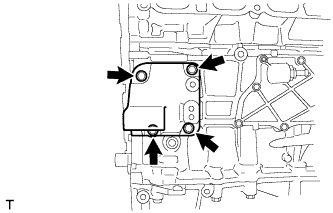
INSTALL OIL PUMP ASSEMBLY
-
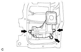
Install the oil pump with the 3 bolts.
- Torque:
- 21 N*m { 214 kgf*cm, 15 ft.*lbf }
-
-
INSTALL NO. 2 OIL PAN SUB-ASSEMBLY
-
Remove any old packing material and be careful not to drop any oil on the contact surfaces of the cylinder block and oil pan.
-
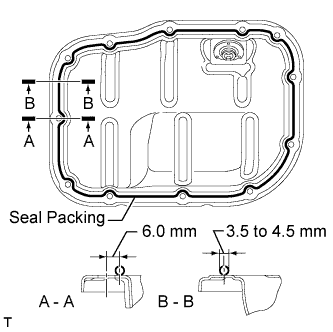
Apply seal packing in a continuous line as shown in the illustration.
Application Specification Area Seal Packing Diameter Distance from Center of Bolt Hole to Center of Seal Packing A - A 3.0 to 4.5 mm (0.118 to 0.177 in.) 6.0 mm (0.236 in.) B - B - Seal packing Toyota Genuine Seal Packing Black, Three Bond 1207B or equivalent Note
-
Remove any oil from the contact surfaces.
-
Install the oil pan within 3 minutes and tighten the bolts within 10 minutes after applying seal packing.
-
Do not add engine oil for at least 2 hours after installing the oil pan.
-
-
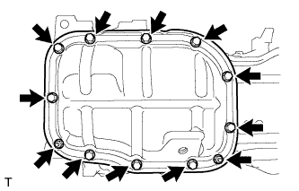
Install the No. 2 oil pan with the 10 bolts and 2 nuts.
- Torque:
- 10 N*m { 102 kgf*cm, 7 ft.*lbf }
-
-
INSTALL OIL PAN DRAIN PLUG
-
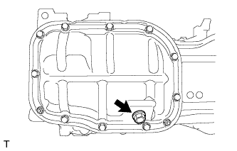
Install a new gasket and the drain plug.
- Torque:
- 37 N*m { 377 kgf*cm, 27 ft.*lbf }
-
-
INSTALL ENGINE REAR OIL SEAL
-
Apply MP grease to the lip of a new oil seal.
Note
-
Do not allow foreign matter to contact the lip of the oil seal.
-
Do not allow MP grease to contact the dust seal.
-
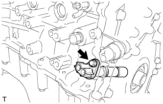
-
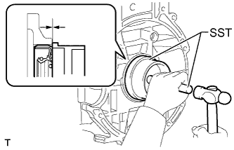
Using SST and a hammer, tap in the oil seal until its surface is flush with the edges of the cylinder block and crankcase.
- SST
- 09223-15030
- 09950-70010 ( 09951-07100 )
Note
-
Wipe off any extra grease from the crankshaft.
-
Do not tap in the oil seal at an angle.
-
-
INSTALL NO. 1 TAPER SCREW PLUG
-
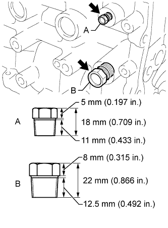
Apply adhesive to 2 or 3 threads of the No. 1 taper screw plug, and install the No. 1 taper screw plug (A).
- Torque:
- 25 N*m { 255 kgf*cm, 18 ft.*lbf }
Adhesive Toyota Genuine Adhesive 1344, Three Bond 1344 or equivalent Note
-
Install the plug within 3 minutes of applying adhesive.
-
Do not start the engine within 1 hour of installing the plug.
-
Apply adhesive to 2 or 3 threads of the No. 1 taper screw plug, and install the No. 1 taper screw plug (B).
- Torque:
- 43 N*m { 438 kgf*cm, 32 ft.*lbf }
Adhesive Toyota Genuine Adhesive 1324, Three Bond 1324 or equivalent Note
-
Install the plug within 3 minutes of applying adhesive.
-
Do not start the engine within 1 hour of installing the plug.
-
-
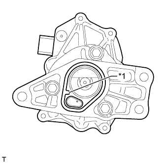
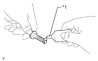
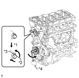
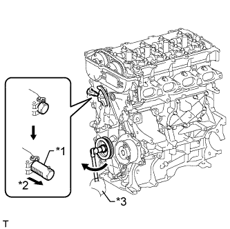
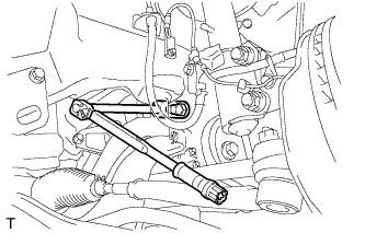
INSTALL VENTILATION VALVE SUB-ASSEMBLY
-
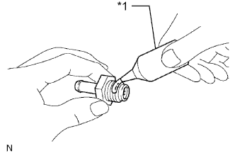
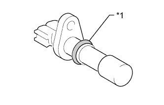
Text in Illustration *1 Adhesive Apply adhesive to 2 or 3 threads of the ventilation valve sub-assembly.
Adhesive Toyota genuine adhesive 1324, three bond 1324 or equivalent -
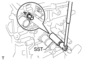
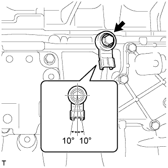
Using a 22 mm ball joint lock nut wrench, install the ventilation valve sub-assembly.
- Torque:
- 20 N*m { 204 kgf*cm, 15 ft.*lbf }
Note
Use the formula to calculate special torque values for situations where ball joint lock nut wrench is combined with a torque wrench Click here.
-
-
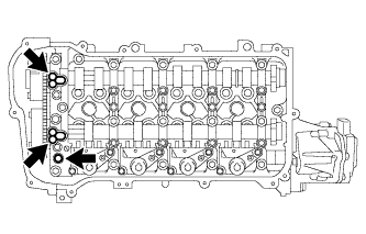
INSTALL CYLINDER HEAD GASKET
-
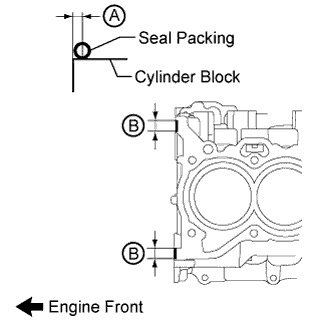
Apply seal packing to the cylinder block as shown in the illustration.
Seal packing Toyota Genuine Seal Packing Black, Three Bond 1207B or equivalent Standard seal packing diameter 4.0 mm (0.157 in.) Application Specification Area Seal Packing Application Length Distance from Edge of Cylinder Block to Center of Seal Packing A - 2.0 to 4.0 mm (0.0787 to 0.157 in.) B 10 to 15 mm (0.394 to 0.591 in.) - Note
Remove any oil from the cylinder block.
-
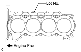
Place a new cylinder head gasket on the cylinder block with the Lot No. stamp facing upward.
Note
Install the cylinder head gasket within 3 minutes after applying seal packing.
-
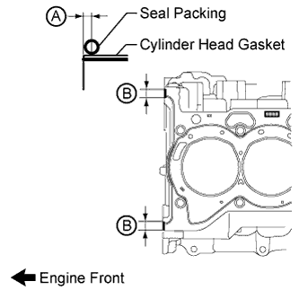
Apply seal packing to the cylinder head gasket as shown in the illustration.
Seal packing Toyota Genuine Seal Packing Black, Three Bond 1207B or equivalent Standard seal packing diameter 4.0 mm (0.157 in.) Application Specification Area Seal Packing Application Length Distance from Edge of Cylinder Head Gasket to Center of Seal Packing A - 2.0 to 4.0 mm (0.0787 to 0.157 in.) B 10 to 15 mm (0.394 to 0.591 in.) - Note
-
Remove any oil from the cylinder head gasket and cylinder head.
-
Install the cylinder head within 3 minutes and tighten the bolts within 15 minutes of applying seal packing.
-
-
-
INSTALL CYLINDER HEAD SUB-ASSEMBLY
Tech Tips
The cylinder head bolts are tightened in 3 progressive steps.
-
Place the cylinder head on the cylinder block.
Note
-
Make sure that no oil is on the mounting surface of the cylinder head.
-
Place the cylinder head on the cylinder block gently in order not to damage the gasket with the bottom part of the head.
-
-
Install the plate washers to the cylinder head bolts.
-
Apply a light coat of engine oil to the threads and under the heads of the cylinder head bolts.
-
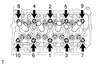
Step 1:
-
Using a 10 mm bi-hexagon wrench, install and uniformly tighten the 10 cylinder head bolts in several steps, in the sequence shown in the illustration.
- Torque:
- 49 N*m { 500 kgf*cm, 36 ft.*lbf }
Note
Do not drop the plate washers into the cylinder head.
-
-
Step 2:
-
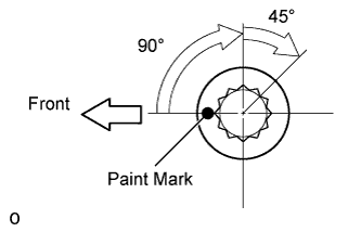
Mark each cylinder head bolt head with paint as shown in the illustration.
-
Tighten the cylinder head bolts 90° in the sequence shown in step 1.
-
-
Step 3:
-
Tighten the cylinder head bolts another 45° in the sequence shown in step 1.
-
-
Check that the paint mark is now at a 135° angle to the front.
-
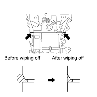
After tightening the cylinder head bolts, wipe off the seal packing material that has seeped out from between the contact surfaces of the cylinder head and cylinder block.
-
-
INSTALL VALVE STEM CAP
-
Apply a light coat of engine oil to the valve stem ends.
-
Install the 16 valve stem caps to the cylinder head.
Note
Do not drop the valve stem caps into the cylinder head.
-
-
INSTALL VALVE LASH ADJUSTER ASSEMBLY
-
Inspect each valve lash adjuster before installing it Click here.
-
Install the 16 valve lash adjusters to the cylinder head.
Note
Install the valve lash adjuster to the same place it was removed from.
-
-
INSTALL NO. 1 VALVE ROCKER ARM SUB-ASSEMBLY
-
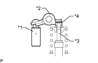
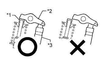
Text in Illustration *1 Lash Adjuster *2 Valve Rocker Arm *3 Valve Stem *4 Valve Stem Cap Apply engine oil to the valve lash adjuster tips and valve stem cap ends.
-
Make sure that the No. 1 valve rocker arms are installed as shown in the illustration.
-
-
INSTALL CAMSHAFT HOUSING STRAIGHT PIN
Note
It is not necessary to remove a straight pin unless it is being replaced.
-
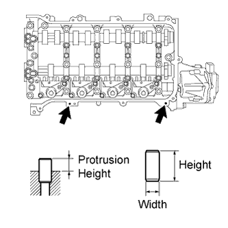
Using a plastic-faced hammer, tap in a new straight pin to the specified protrusion height.
Standard Ring Pin Item Protrusion Height Height Width Straight pin 6.5 to 7.5 mm (0.256 to 0.295 in.) 14 mm (0.551 in.) 6.0 mm (0.236 in.)
-
-
INSTALL CAMSHAFT HOUSING STUD BOLT
Note
If a stud bolt is deformed or the threads are damaged, replace it.
-
Using an E7 "TORX" socket wrench, install the camshaft housing stud bolts.
- Torque:
- 9.5 N*m { 97 kgf*cm, 84 in.*lbf }
-
-
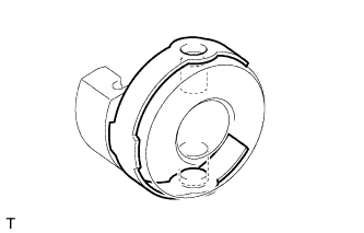
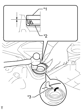
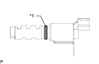
INSTALL CONTINUOUSLY VARIABLE VALVE LIFT CONTROLLER ASSEMBLY
-
Text in Illustration *1 Protrusion Install a new O-ring to the continuously variable valve lift controller.
Note
-
Align the protrusion of the O-ring with the protrusion of the continuously variable valve lift controller.
-
Make sure that the O-ring is not protruding from the groove in the continuously variable valve lift controller.
-
-
Install the control actuator clip to the control actuator connector.
Tech Tips
When the continuously variable valve lift controller is new, a control actuator connector is attached to it. Remove the control actuator connector before performing these procedures.
Note
Be sure to insert the protrusions of the control actuator clip into the holes in the control actuator connector.
-
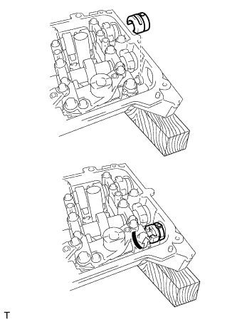
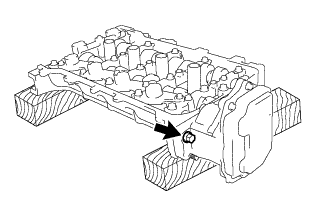
Install the control actuator connector to the valve rocker shaft and rotate the control actuator connector as shown in the illustration.
-
Insert the continuously variable valve lift controller into the camshaft housing.
-
Install the continuously variable valve lift controller to the camshaft housing with the bolt.
- Torque:
- 18 N*m { 184 kgf*cm, 13 ft.*lbf }
Note
Do not let the O-ring become jammed between parts.
-
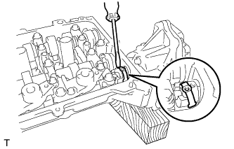
Using a screwdriver, slide the control actuator clip from the control actuator connector.
-
Slide only the upper part of the control actuator clip as the straight pin may fall if the control actuator clip is completely removed.
-
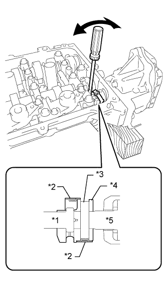
Text in Illustration *1 Rocker Shaft *2 Clip *3 Straight Pin Hole *4 Connector *5 Controller Shaft Using a screwdriver, lightly pry the control actuator connector and align the hole in the control actuator connector with the hole in the continuously variable valve lift controller.
Note
-
Do not forcefully pry the control actuator connector.
-
Do not damage the camshaft housing or camshaft bearing cap.
-
-
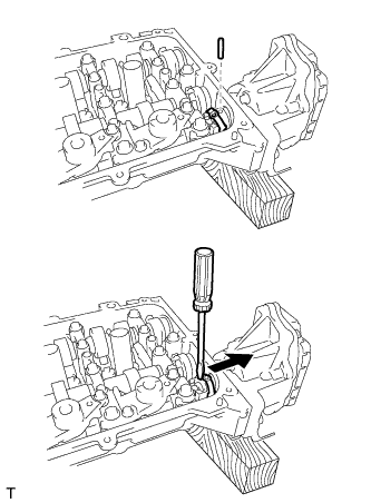
Insert the straight pin into the control actuator connector.
Note
Do not use a tool to insert the straight pin. Insert the straight pin by hand.
Tech Tips
If the straight pin is difficult to insert, insert the straight pin while lightly prying the control actuator connector.
-
Using a screwdriver, install the control actuator clip to the control actuator connector.
Note
Insert the protrusion of the control actuator clip into the hole in the control actuator connector.
-
-
INSTALL CAMSHAFT HOUSING SUB-ASSEMBLY
-
Text in Illustration *1 Valve Stem Cap *2 Valve Rocker Arm *3 Valve Lash Adjuster Check that the valve rocker arms are installed as shown in the illustration.
-
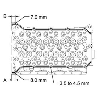
Apply seal packing in a continuous line as shown in the illustration.
Seal packing Toyota Genuine Seal Packing Black, Three Bond 1207B or equivalent Standard Seal Diameter Area Specified Condition Continuous line 3.5 to 4.5 mm (0.138 to 0.177 in.) A 8.0 mm (0.315 in.) B 7.0 mm (0.276 in.) Application Length A and B 15 mm (0.591 in.) Note
-
Remove any oil from the contact surfaces.
-
Install the camshaft housing within 3 minutes and tighten the bolts within 10 minutes after applying seal packing.
-
Do not start the engine for at least 2 hours after installation.
-
-
Set the camshaft and No. 2 camshaft as shown in the illustration.
-
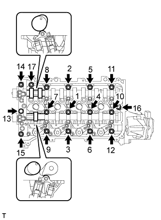
Install the camshaft housing with the 17 bolts and tighten them in the order shown in the illustration.
- Torque:
- 27 N*m { 275 kgf*cm, 20 ft.*lbf }
Note
-
After installing the camshaft housing, make sure that the cam lobes are positioned as shown in the illustration.
-
If any of the bolts are loosened during installation, remove the camshaft housing, clean the installation surfaces, and reapply seal packing.
-
If the camshaft housing is removed because any of the bolts are loosened during installation, make sure that the previously applied seal packing does not enter any oil passages.
-
After installing the camshaft housing, wipe off any seal packing that seeped out from between the housing and cylinder head.
-
-
INSTALL CAMSHAFT TIMING EXHAUST GEAR ASSEMBLY
-
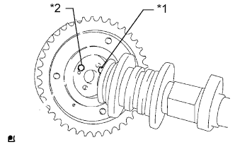
Text in Illustration *1 Straight Pin *2 Pin Hole Put the camshaft timing exhaust gear and camshaft together by aligning the pin hole and straight pin.
Note
Do not forcefully push in the camshaft timing exhaust gear. This may cause the camshaft straight pin tip to damage the installation surface of the camshaft timing exhaust gear.
-
Lightly press the gear against the camshaft and turn the gear. Push further at the position where the pin enters the hole.
Note
Be sure not to turn the camshaft timing exhaust gear in the retard direction (clockwise).
-
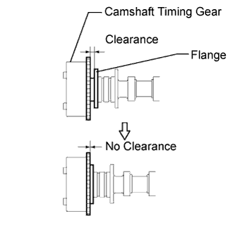
Check that there is no clearance between the gear and camshaft flange.
-
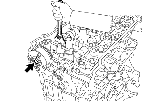
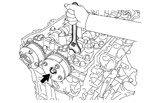
Tighten the flange bolt with the camshaft timing exhaust gear secured in place.
- Torque:
- 54 N*m { 551 kgf*cm, 40 ft.*lbf }
-
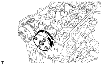
Check the camshaft timing exhaust gear lock.
-
Make sure that the camshaft timing exhaust gear is locked.
-
-
-
INSTALL CAMSHAFT TIMING GEAR ASSEMBLY
-
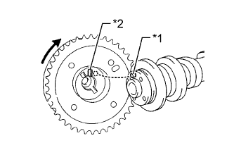
Text in Illustration *1 Straight Pin *2 Key Groove Put the camshaft timing gear and camshaft together with the straight pin and key groove misaligned as shown in the illustration.
Note
Do not forcefully push in the camshaft timing gear. This may cause the camshaft straight pin tip to damage the installation surface of the camshaft timing gear.
-
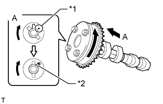
Text in Illustration *1 Straight Pin *2 Key Groove Turn the camshaft timing gear as shown in the illustration while pushing it gently against the camshaft. Push further at the position where the pin fits into the groove.
Note
Do not turn the camshaft timing gear in the retard direction (clockwise).
-
Check that there is no clearance between the camshaft timing gear and camshaft flange.
-
Tighten the flange bolt with the camshaft timing gear secured in place.
- Torque:
- 54 N*m { 551 kgf*cm, 40 ft.*lbf }
-
Text in Illustration *1 Lock Check that the camshaft timing gear can move in the retard direction (clockwise) and is locked in the most retarded position.
-
-
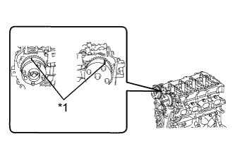
INSTALL CRANKSHAFT TIMING GEAR KEY
-
Using a plastic-faced hammer, tap in the 2 crankshaft timing gear keys.
Tech Tips
Tap in the crankshaft timing gear keys until they contact the crankshaft as shown in the illustration.
-
-
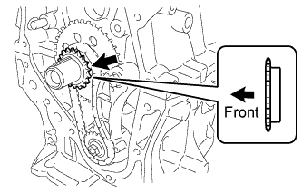
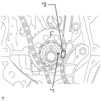
INSTALL NO. 1 CRANKSHAFT POSITION SENSOR PLATE
-
Install the crankshaft position sensor plate with the "F" mark facing forward.
-
-
INSTALL NO. 2 CHAIN SUB-ASSEMBLY
-
Temporarily install the crankshaft pulley bolt.
-
Set the crankshaft key as shown in the illustration.
-
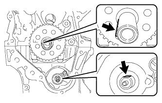
Turn the drive shaft so that the cutout faces upward.
-
Remove the crankshaft pulley bolt.
-
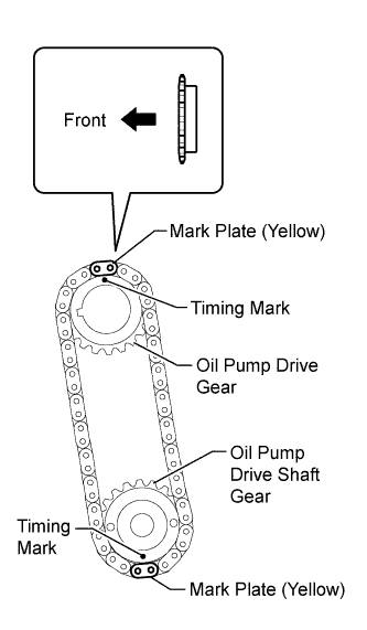
Align the yellow mark plates with the timing mark of each gear as shown in the illustration.
-
Install the gears onto the crankshaft and oil pump shaft with the chain on the gears.
-
Temporarily install the oil pump drive shaft gear with the nut.
-
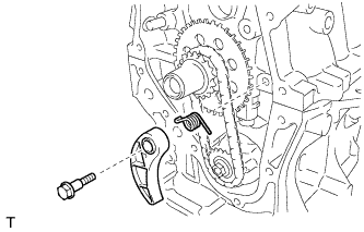
Install the damper spring to the chain tensioner plate, and then install the chain tensioner plate with the bolt.
- Torque:
- 10 N*m { 102 kgf*cm, 7 ft.*lbf }
-
Temporarily install the crankshaft pulley with the pulley bolt.
-
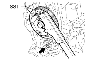
Using SST, hold the crankshaft. Then tighten the drive shaft gear nut.
- SST
- 09330-00021
- 09213-58014 ( 91551-80840 )
- Torque:
- 28 N*m { 286 kgf*cm, 21 ft.*lbf }
-
Remove SST, the crankshaft pulley bolt and crankshaft pulley.
-
-
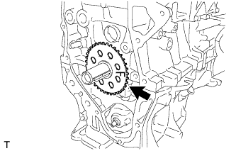
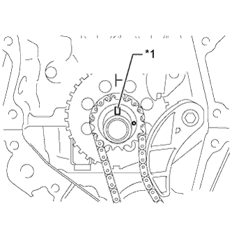
INSTALL CRANKSHAFT TIMING SPROCKET
-
Install the crankshaft timing sprocket as shown in the illustration.
-
-
INSTALL NO. 1 CHAIN VIBRATION DAMPER
-
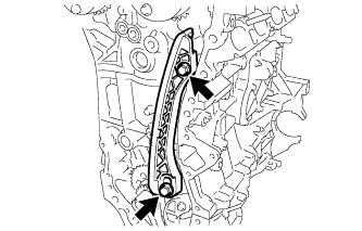
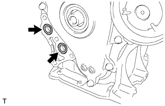
Install the chain vibration damper with the 2 bolts.
- Torque:
- 21 N*m { 214 kgf*cm, 15 ft.*lbf }
-
-
SET NO. 1 CYLINDER TO TDC/COMPRESSION
-
Text in Illustration *1 Timing Gear Key Temporarily install the crankshaft pulley bolt.
-
Turn the crankshaft counterclockwise to position the timing gear key at the top.
-
Text in Illustration *1 Timing Mark Check that the timing marks on the camshaft timing gears are aligned as shown in the illustration.
-
Remove the crankshaft pulley bolt.
-
-
INSTALL CHAIN SUB-ASSEMBLY
-
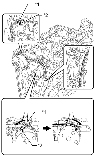
Text in Illustration *1 Mark Plate (Orange) *2 Timing Mark Align the mark plate (orange) with the timing mark as shown in the illustration and install the chain.
Tech Tips
-
Be sure to position the mark plate at the front of the engine.
-
The mark plate on the camshaft side is colored orange.
-
Do not pass the chain around the sprocket of the camshaft timing gear. Only place it on the sprocket.
-
Pass the chain through the No. 1 vibration damper.
-
-
Hold the hexagonal portion of the camshaft with a wrench and turn the camshaft timing gear counterclockwise to align the mark plate (orange) and timing mark, and then install the chain.
-
Hold the hexagonal portion of the camshaft with a wrench and turn the camshaft timing gear clockwise.
Tech Tips
To tension the chain, slowly turn the camshaft timing gear clockwise to prevent the chain from being misaligned.
-
Text in Illustration *1 Timing Mark *2 Mark Plate (Pink) Align the mark plates (pink) and timing marks and install the chain to the crankshaft timing gear.
Tech Tips
The mark plates on the crankshaft side are colored pink.
-
-
INSTALL CHAIN TENSIONER SLIPPER
-
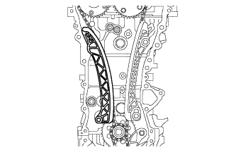
Install the chain tensioner slipper to the cylinder block.
-
-
CHECK NO. 1 CYLINDER TO TDC/COMPRESSION
-
Check each timing mark at TDC/compression.
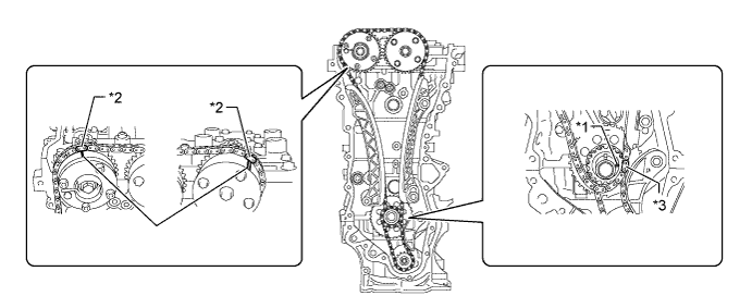
Text in Illustration *1 Timing Mark *2 Mark Plate (Orange) *3 Mark Plate (Pink) -
-
-
INSTALL NO. 1 GENERATOR BRACKET
-
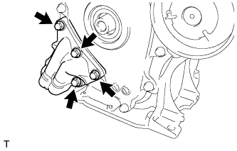
Install the generator bracket with the 4 bolts.
- Torque:
- 21 N*m { 214 kgf*cm, 15 ft.*lbf }
-
-
INSTALL WATER INLET HOUSING STUD BOLT
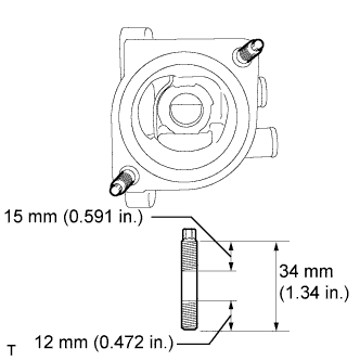
Note
If a stud bolt is deformed or the threads are damaged, replace it.
-
Using an E5 "TORX" socket wrench, install the stud bolts as shown in the illustration.
- Torque:
- 5.0 N*m { 51 kgf*cm, 44 in.*lbf }
-
-
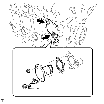
INSTALL WATER INLET HOUSING
-
Install a new gasket and the water inlet housing with the 3 bolts.
- Torque:
- 21 N*m { 214 kgf*cm, 15 ft.*lbf }
-
-
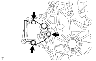
INSTALL TIMING CHAIN COVER SUB-ASSEMBLY
-
Install a new gasket.
Note
Remove any oil from the contact surface.
-
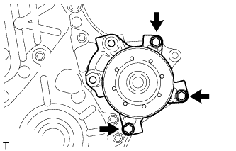
Install the water pump with the 3 bolts.
- Torque:
- 21 N*m { 214 kgf*cm, 15 ft.*lbf }
-
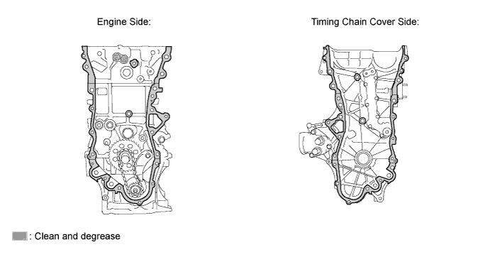
Remove any old packing (FIPG) material and be careful not to drop any oil on the contact surfaces of the timing chain cover, cylinder head, camshaft housing, stiffening crankcase and cylinder block.
-
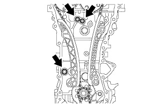
Install 3 new O-rings.
-
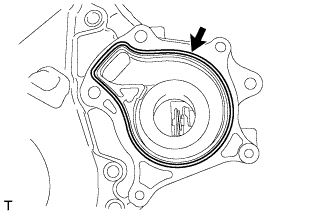
Apply seal packing as shown in the illustration.
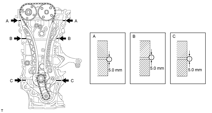
Seal packing Toyota Genuine Seal Packing Black, Three Bond 1207B or equivalent Standard seal diameter 5.0 mm (0.197 in.) Note
-
Remove any oil from the contact surface.
-
Install the timing chain cover within 3 minutes and tighten the bolts within 10 minutes after applying seal packing.
-
Do not add engine oil for at least 2 hours after installing the timing chain cover.
-
-
Apply seal packing to the timing chain cover in a continuous line as shown in the following illustration.
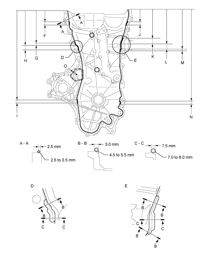
Seal Packing Item Seal Packing Dashed line Toyota Genuine Seal Packing Black, Three Bond 1207B or equivalent Continuous line Alternate long and short dashed line Toyota Genuine Seal Packing 1282B, Three Bond 1282B or equivalent Application Specification Area Seal Packing Diameter Distance from Edge of Cover to: Seal Packing Application Length Distance from Top of Cover to Top of Seal Packing Dashed line 2.5 to 3.0 mm (0.0984 to 0.118 in.) Center of seal packing
2.5 mm (0.0984 in.)
- - Continuous line 4.5 to 5.5 mm (0.177 to 0.217 in.) or 7.0 to 8.0 mm (0.276 to 0.315 in.) - - - Alternate long and short dashed line 4.0 mm (0.157 in.) Center of seal packing
3.0 mm (0.118 in.)
- - A - A 2.5 to 3.0 mm (0.0984 to 0.118 in.) Center of seal packing
2.5 mm (0.0984 in.)
- - B - B 4.5 to 5.5 mm (0.177 to 0.217 in.) Opposite edge of seal packing
5.0 mm (0.197 in.)
- - C - C 7.0 to 8.0 mm (0.276 to 0.315 in.) Opposite edge of seal packing
7.5 mm (0.295 in.)
- - F 4.5 to 5.5 mm (0.177 to 0.217 in.) - 15.5 mm (0.610 in.) 50.4 mm (1.98 in.) G 4.5 to 5.5 mm (0.177 to 0.217 in.) - 10.3 mm (0.406 in.) 143.1 mm (5.63 in.) H 7.0 to 8.0 mm (0.276 to 0.315 in.) - 19.5 mm (0.768 in.) 153.4 mm (6.04 in.) I 4.5 to 5.5 mm (0.177 to 0.217 in.) - 16.0 mm (0.630 in.) 385.8 mm (1.27 ft.) J 4.5 to 5.5 mm (0.177 to 0.217 in.) - 18.6 mm (0.732 in.) 51.4 mm (2.02 in.) K 4.5 to 5.5 mm (0.177 to 0.217 in.) - 25.3 mm (0.996 in.) 121.9 mm (4.80 in.) L 7.0 to 8.0 mm (0.276 to 0.315 in.) - 25.8 mm (1.02 in.) 147.2 mm (5.80 in.) M 4.5 to 5.5 mm (0.177 to 0.217 in.) - 5.1 mm (0.201 in.) 173.0 mm (6.81 in.) N 4.5 to 5.5 mm (0.177 to 0.217 in.) - 14.6 mm (0.575 in.) 385.8 mm (1.27 ft.) O 4.0 mm (0.157 in.) Center of seal packing
3.0 mm (0.118 in.)
- - Note
-
When the contact surfaces are wet, wipe them with oil-free cloth before applying seal packing.
-
Install the timing chain cover within 3 minutes and tighten the bolts within 10 minutes after applying seal packing.
-
After applying seal packing to the timing chain cover, install the engine mounting bracket and oil filter bracket within 10 minutes.
-
Do not add engine oil for at least 2 hours after installation.
-
-
Clean the bolts and their installation holes.
-
Install the timing chain cover.
-
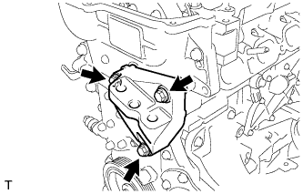
Temporarily install the engine mounting bracket with the 3 bolts.
Note
-
Install the mounting bracket within 10 minutes after installing the timing chain cover.
-
Do not add engine oil for at least 2 hours after installation.
-
-
Install 2 new O-rings.
-
Temporarily install the oil filter bracket with the 4 bolts.
Note
-
Install the oil filter bracket within 10 minutes after installing the timing chain cover.
-
Do not add engine oil for at least 2 hours after installation.
-
-
Text in Illustration *1 Adhesive Apply adhesive to 5 and a half threads or more of the end of bolt E.
Adhesive Toyota Genuine Adhesive 1324, Three Bond 1324 or equivalent -
Install the timing chain cover with the 26 bolts and seal washer in the order shown in the illustration.
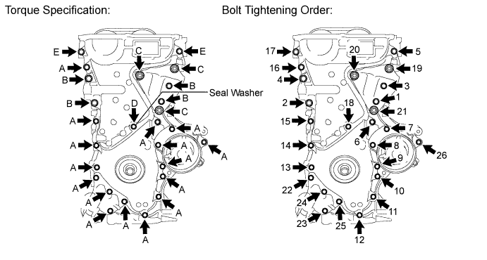
- Torque:
- for bolt A, E
- 26 N*m { 260 kgf*cm, 19 ft.*lbf }
- for bolt B
- 51 N*m { 520 kgf*cm, 38 ft.*lbf }
- for bolt C
- 51 N*m { 520 kgf*cm, 38 ft.*lbf }
- for bolt D
- 10 N*m { 102 kgf*cm, 7 ft.*lbf }
Note
-
When the contact surfaces are wet, wipe them with oil-free cloth before applying seal packing.
-
Install the timing chain cover within 3 minutes and tighten the bolts within 10 minutes after applying the seal packing.
-
Do not add engine oil for at least 2 hours after installation.
Bolt Length Item Length Thread Diameter Bolt A, E 35 mm (1.38 in.) 8 mm (0.315 in.) Bolt B 55 mm (2.17 in.) 10 mm (0.394 in.) Bolt C 80 mm (3.15 in.) 10 mm (0.394 in.) Bolt D 40 mm (1.57 in.) 6 mm (0.236 in.) Tech Tips
Apply adhesive to bolt E before installing it.
-
-
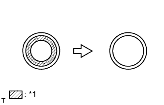
INSTALL TIMING CHAIN COVER OIL SEAL
-
Apply MP grease to the lip of a new oil seal.
Note
-
Do not allow foreign matter to contact the lip of the oil seal.
-
Do not allow MP grease to contact the dust seal.
-
-
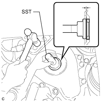
Using SST and a hammer, tap in the oil seal until its surface is flush with the timing chain cover edge.
- SST
- 09223-22010
Note
-
Wipe off any extra grease from the crankshaft.
-
Do not tap in the oil seal at an angle.
-
-
INSTALL ENGINE MOUNTING BRACKET STUD BOLT
Note
If a stud bolt is deformed or the threads are damaged, replace it.
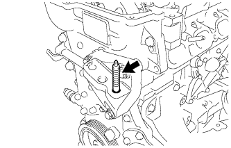
-
Install the stud bolt.
- Torque:
- 10 N*m { 102 kgf*cm, 7 ft.*lbf }
-
-
INSTALL CRANKSHAFT PULLEY
-
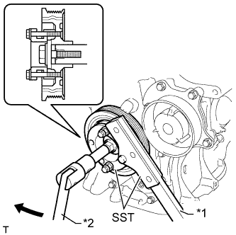
Text in Illustration *1 Hold *2 Turn Align the key groove of the pulley with the pulley set key.
-
Temporarily install the pulley with the pulley bolt.
-
Using SST, hold the pulley in place and tighten the bolt.
- SST
- 09330-00021
- 09213-58014 ( 91551-80840 )
- Torque:
- 190 N*m { 1940 kgf*cm, 140 ft.*lbf }
-
-
INSTALL NO. 1 CHAIN TENSIONER ASSEMBLY
-
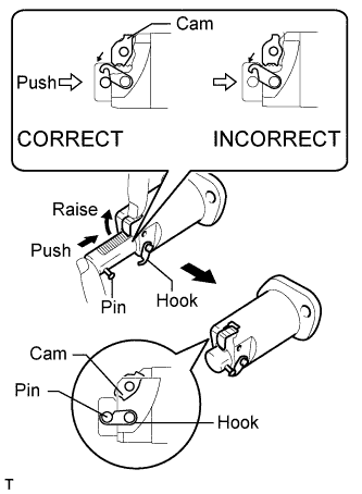
Release the cam, and then fully push in the plunger and engage the hook to the pin so that the plunger is in the position shown in the illustration.
Note
Make sure that the cam engages the first tooth of the plunger to allow the hook to pass over the pin.
-
Install a new gasket, the chain tensioner and bracket with the 2 nuts.
- Torque:
- 12 N*m { 122 kgf*cm, 9 ft.*lbf }
Note
If the hook releases the plunger while the chain tensioner is being installed, set the hook again.
-
Text in Illustration *1 Release *2 Pin *3 Hook *4 Turn Rotate the crankshaft counterclockwise slightly and check that the hook becomes released.
-
Text in Illustration *1 Plunger *2 Plunger Extended *3 Turn Turn the crankshaft clockwise and check that the plunger is extended.
-
-
INSTALL OIL FILTER CAP ASSEMBLY
-
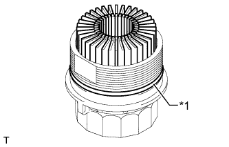
Clean the inside of the oil filter cap, its threads and O-ring groove.
-
Apply a small amount of engine oil to a new O-ring and install it to the oil filter cap.
Text in Illustration *1 O-Ring -
Set a new oil filter element in the oil filter cap.
-
Remove any dirt or foreign matter from the installation surface and inside of the engine.
-
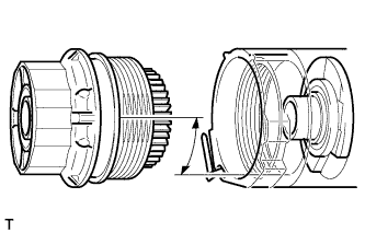
Reapply a small amount of engine oil to the O-ring of the oil filter cap. Align the oil filter cap with the oil filter bracket so that the cutout portion of the cap threads is in a position 90° from the groove in the bracket, and then temporarily install the cap.
Note
Make sure that the O-ring does not get caught between the parts.
-
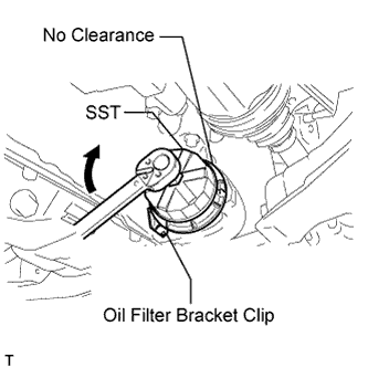
Using SST, tighten the oil filter cap.
- SST
- 09228-06501
- Torque:
- 25 N*m { 255 kgf*cm, 18 ft.*lbf }
Note
-
After tightening the oil filter cap, check for gaps between the installation surfaces.
-
Do not remove the oil filter bracket clip when installing the oil filter cap.
-
Do not cross thread the oil filter cap.
-
-
INSTALL SPARK PLUG TUBE GASKET
-
Text in Illustration *1 Part to Cut Off Using a cutter knife, cut off the seal part of the removed gasket.
-
Text in Illustration *1 Plug Tube Gasket without Sealing Part *2 New Plug Tube Gasket *3 Claw Using a hammer and a plug tube gasket which has had the sealing part cut off, uniformly tap in a new plug tube gasket all the way.
Tech Tips
If a plug tube gasket that will be used to install a new gasket is deformed and cannot be positioned on a new gasket, correct the deformation using pliers.
Note
-
Keep the lip free of foreign matter.
-
Do not tap in the plug tube gasket at an angle.
-
-
Return the claws of the ventilation baffle plate to their original positions.
-
-
INSTALL CYLINDER HEAD COVER GASKET
-
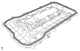
Install a new cylinder head cover gasket to the cylinder head cover.
Note
Remove any oil from the contact surfaces.
-
-
INSTALL CYLINDER HEAD COVER SUB-ASSEMBLY
-
Install 3 new gaskets to the camshaft bearing cap.
-
Apply seal packing as shown in the illustration.
Seal packing Toyota Genuine Seal Packing Black, Three Bond 1207B or equivalent Standard diameter 4.0 mm (0.157 in.) Note
-
Remove any oil from the contact surfaces.
-
Install the cylinder head cover sub-assembly within 3 minutes and tighten the bolts within 15 minutes after applying seal packing.
-
Do not start the engine for at least 2 hours after the installation.
-
-
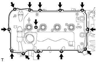
Install the cylinder head cover with a new seal washer and the 13 bolts.
- Torque:
- 10 N*m { 102 kgf*cm, 7 ft.*lbf }
-
-
INSTALL ENGINE OIL PRESSURE SWITCH ASSEMBLY
-
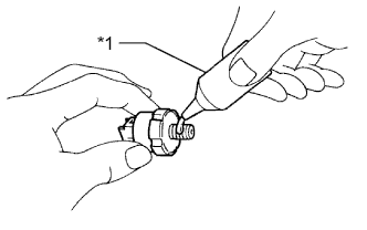
Text in Illustration *1 Adhesive Apply adhesive to 2 or 3 threads of the oil pressure switch.
Adhesive Toyota Genuine Adhesive 1344, Three Bond 1344 or equivalent Note
Do not let adhesive adhere to the oil hole.
-
Using a 22 mm deep socket wrench, install the oil pressure switch.
- Torque:
- 15 N*m { 153 kgf*cm, 11 ft.*lbf }
Note
Do not start the engine for at least 1 hour after installation.
-
Connect the oil pressure switch connector.
-
-
INSTALL ENGINE COOLANT TEMPERATURE SENSOR
-
Using SST, install a new gasket engine coolant temperature sensor.
- SST
- 09817-33190
- Torque:
- 20 N*m { 204 kgf*cm, 15 ft.*lbf }
-
-
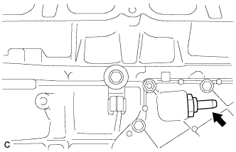
INSTALL KNOCK SENSOR
-
Install the knock sensor with the bolt.
- Torque:
- 21 N*m { 214 kgf*cm, 15 ft.*lbf }
Note
Make sure that the knock sensor is in the correct position.
-
-
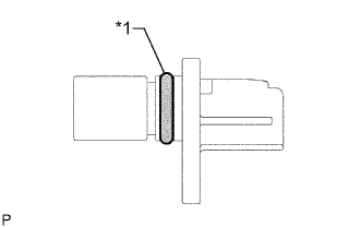
INSTALL CRANKSHAFT POSITION SENSOR
-
Text in Illustration *1 O-Ring Apply a light coat of engine oil to the O-ring of the sensor.
-
Install the crankshaft position sensor with the bolt.
- Torque:
- 10 N*m { 102 kgf*cm, 7 ft.*lbf }
-
-
INSTALL CAMSHAFT TIMING OIL CONTROL VALVE ASSEMBLY
-
Text in Illustration *1 New O-Ring Apply a light coat of engine oil to 2 new O-rings and install them to the camshaft timing oil control valves.
-
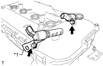
Text in Illustration *1 Bracket Install the 2 camshaft timing oil control valves and bracket with the 2 bolts.
- Torque:
- 10 N*m { 102 kgf*cm, 7 ft.*lbf }
Note
-
Do not allow foreign matter to contact the oil seal face of the oil control valve (connecting surface with cylinder head cover).
-
Be careful that the O-ring is not cracked or moved out of place when installing the oil control valve.
-
-
INSTALL CAMSHAFT POSITION SENSOR
-
Text in Illustration *1 O-Ring Apply a light coat of engine oil to the O-rings of the sensors.
-
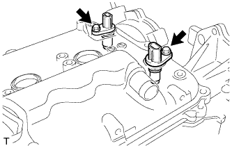
Install the 2 camshaft position sensors with the 2 bolts.
- Torque:
- 10 N*m { 102 kgf*cm, 7 ft.*lbf }
Note
Make sure that the O-ring is not cracked or jammed when installing the sensor.
-
-
INSTALL SPARK PLUG
-
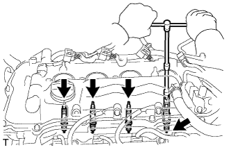
Using a 14 mm spark plug wrench and 100 mm extension bar, install the 4 spark plugs.
- Torque:
- 20 N*m { 204 kgf*cm, 15 ft.*lbf }
-
-
INSTALL ENGINE COVER JOINT
-
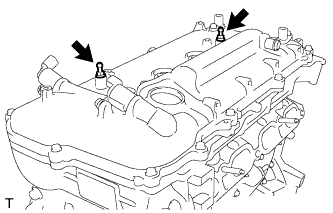
Install the 2 engine cover joints.
- Torque:
- 10 N*m { 102 kgf*cm, 7 ft.*lbf }
-
-
INSTALL OIL FILLER CAP GASKET
-
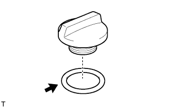
Install the gasket to the oil filler cap.
-
-
INSTALL OIL FILLER CAP SUB-ASSEMBLY
-
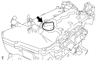
Install the oil filler cap.
-