ENGINE UNIT INSTALLATION

-
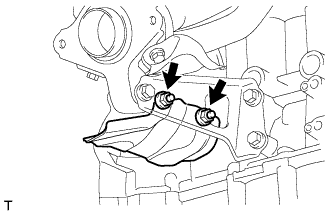
INSTALL NO. 1 VACUUM PUMP BRACKET
-
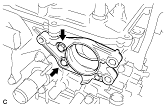
Install a new gasket and the vacuum pump bracket with the 2 bolts.
- Torque:
- 21 N*m { 214 kgf*cm, 15 ft.*lbf }
-
-
INSTALL VACUUM PUMP ASSEMBLY
-
Apply engine oil to 2 new O-rings.
-
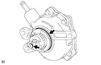
Install the 2 O-rings to the vacuum pump.
-
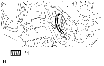
Text in Illustration *1 Engine oil Apply engine oil to the cylinder hollow.
-
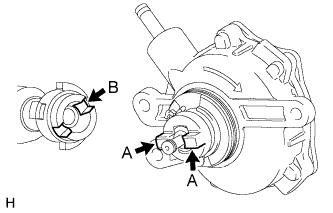
Install the vacuum pump so that the coupling teeth of the vacuum pump (labeled A) and the grooves of the camshaft (labeled B) are aligned.
Note
Be careful not to damage the O-ring.
-
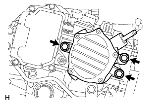
Install the vacuum pump with the 3 bolts.
- Torque:
- 21 N*m { 214 kgf*cm, 15 ft.*lbf }
Note
Confirm that the vacuum pump is not at an angle, and that there is no clearance between the fitting surfaces.
-
-
INSTALL RADIO SETTING CONDENSER
-
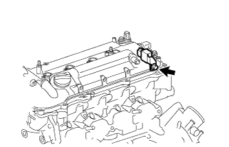
Install the setting condenser with the bolt.
- Torque:
- 10 N*m { 102 kgf*cm, 7 ft.*lbf }
-
-
INSTALL IGNITION COIL ASSEMBLY
-
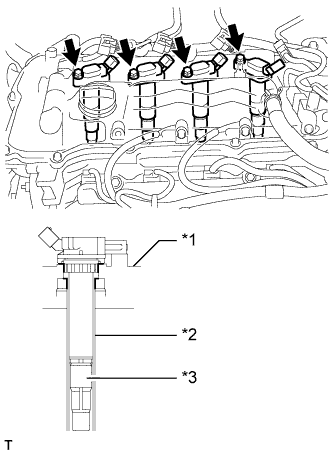
Text in Illustration *1 Cylinder Head Cover *2 Spark Plug Tube *3 Plug Cap Install the 4 ignition coils with the 4 bolts.
- Torque:
- 10 N*m { 102 kgf*cm, 7 ft.*lbf }
Note
When installing the ignition coil, do not damage the plug cap with the cylinder head cover opening or the upper edge of the spark plug tube.
-
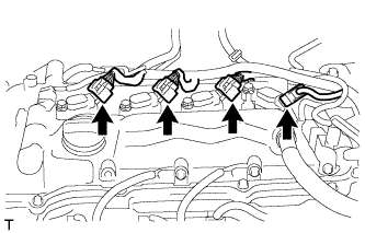
Connect the 4 ignition coil connectors.
-
-
INSTALL THERMOSTAT
-
Install a new gasket to the thermostat.
-
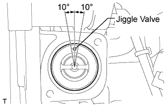
Install the thermostat to the water inlet.
Note
The jiggle valve must be set within 10° on either side of the position shown in the illustration.
-
-
INSTALL WATER INLET
-
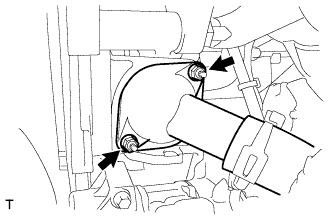
Install the water inlet with the 2 nuts.
- Torque:
- 10 N*m { 102 kgf*cm, 7 ft.*lbf }
-
-
INSTALL WATER INLET HOSE
-
Install the water inlet hose with the 2 clamps.
-
-
INSTALL WATER BY-PASS HOSE
-
Install the water by-pass hose with the clamp.
-
-
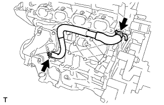
INSTALL NO. 1 WATER BY-PASS PIPE
-
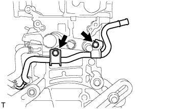
Install the water by-pass pipe with the 2 bolts.
- Torque:
- 21 N*m { 214 kgf*cm, 15 ft.*lbf }
-
-
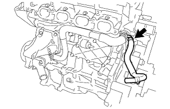
CONNECT NO. 3 WATER BY-PASS HOSE
-
Connect the No. 3 water by-pass hose to the water inlet housing.
-
-
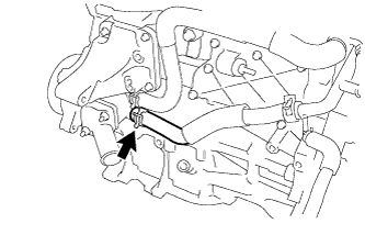
INSTALL VENTILATION HOSE
-
Install the ventilation hose to the ventilation valve.
-
-
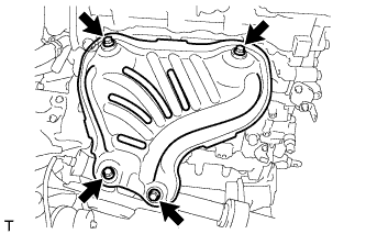
INSTALL EXHAUST MANIFOLD
-
Install a new exhaust manifold gasket.
-
for Nut Type A:
-
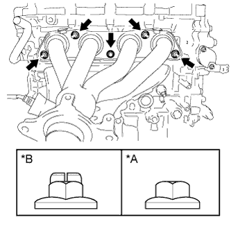
Text in Illustration *A Nut Type A *B Nut Type B Install the exhaust manifold with the 5 nuts.
- Torque:
- 21 N*m { 214 kgf*cm, 15 ft.*lbf }
-
-
for Nut Type B:
-
Install the exhaust manifold with 5 new nuts.
- Torque:
- 37 N*m { 377 kgf*cm, 27 ft.*lbf }
-
-
-
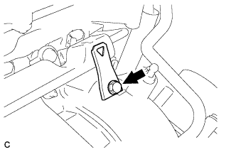
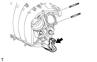
INSTALL MANIFOLD STAY
-
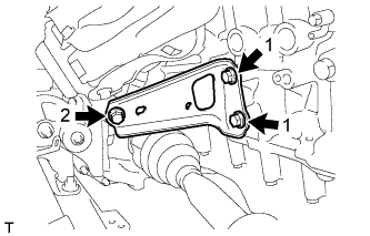
Temporarily install the manifold stay with the 3 bolts.
-
While pushing the manifold stay toward the exhaust manifold, tighten the 2 bolts labeled 1.
- Torque:
- 43 N*m { 438 kgf*cm, 32 ft.*lbf }
-
Tighten the bolt labeled 2.
- Torque:
- 43 N*m { 438 kgf*cm, 32 ft.*lbf }
-
-
INSTALL DRIVE SHAFT HEAT INSULATOR SUB-ASSEMBLY
-
Install the heat insulator with the 2 nuts.
- Torque:
- 18 N*m { 179 kgf*cm, 13 ft.*lbf }
-
-
INSTALL NO. 1 EXHAUST MANIFOLD HEAT INSULATOR
-
Install the heat insulator with the 4 bolts.
- Torque:
- 12 N*m { 122 kgf*cm, 9 ft.*lbf }
-
-
INSTALL ENGINE OIL LEVEL DIPSTICK GUIDE
-
Apply a light coat of engine oil to a new O-ring.
-
Install the O-ring to the dipstick guide.
-
Install the dipstick guide with the bolt.
- Torque:
- 21 N*m { 214 kgf*cm, 15 ft.*lbf }
-
Install the engine oil level dipstick.
-
-
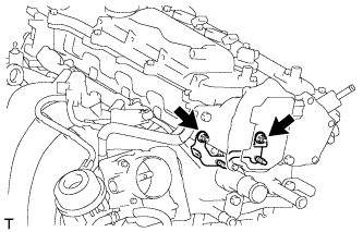
INSTALL FUEL INJECTOR ASSEMBLY
-
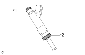
Text in Illustration *1 O-Ring *2 Injector Vibration Insulator Install a new injector vibration insulator to the fuel injector assembly.
-
Apply a light coat of gasoline or spindle oil to the contact surfaces of the O-ring of the fuel injector.
-
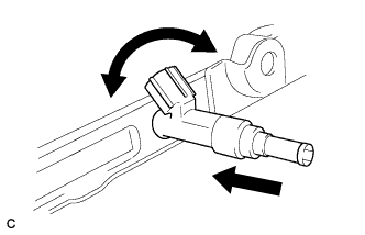
While turning the fuel injector left and right, install it to the fuel delivery pipe.
Note
-
Do not twist the O-ring.
-
After installing the fuel injectors, check that they turn smoothly. If not, replace the O-ring with a new one.
-
-
-
INSTALL NO. 1 DELIVERY PIPE SPACER
-
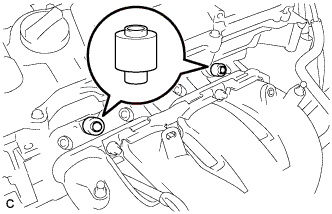
Install the 2 No. 1 delivery pipe spacers to the cylinder head.
Note
Install the No. 1 delivery pipe spacers in the correct direction.
-
-
INSTALL FUEL DELIVERY PIPE SUB-ASSEMBLY
-
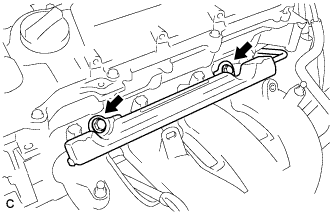
Install the fuel delivery pipe with the 4 fuel injector assemblies, and then temporarily install the 2 bolts.
Note
-
Do not drop the fuel injectors when installing the fuel delivery pipe.
-
Check that the fuel injector assemblies rotate smoothly after installing the fuel delivery pipe.
-
-
Tighten the 2 bolts to the specified torque.
- Torque:
- 21 N*m { 214 kgf*cm, 15 ft.*lbf }
-
Install the bolt to secure the fuel delivery pipe.
- Torque:
- 21 N*m { 214 kgf*cm, 15 ft.*lbf }
-
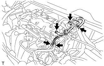
Install the wire harness bracket with the bolt.
- Torque:
- 10 N*m { 102 kgf*cm, 7 ft.*lbf }
-
-
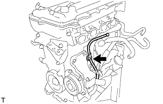
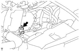
INSTALL FUEL TUBE SUB-ASSEMBLY
-
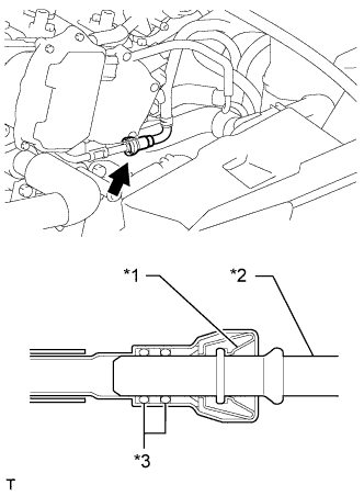
Text in Illustration *1 Retainer *2 Pipe *3 O-Ring Push the fuel tube sub-assembly connector onto the fuel delivery pipe until a "click" sound can be heard.
Note
-
Check that there are no scratches or foreign matter around the contact surfaces of the fuel tube connector and pipe before performing this step.
-
After connecting the fuel tube, check that the fuel tube connector and pipe are securely connected by pulling on them.
-
-
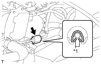
Text in Illustration *1 Claw Install a new No. 2 fuel pipe clamp.
-
-
INSTALL WIRE HARNESS CLAMP BRACKET
-
Install the wire harness clamp bracket with the 2 nuts.
- Torque:
- 18 N*m { 184 kgf*cm, 13 ft.*lbf }
-
-
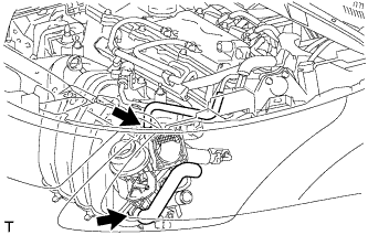
INSTALL AIR TUBE
-
Install the air tube with the 2 bolts.
- Torque:
- 10 N*m { 102 kgf*cm, 7 ft.*lbf }
-
Connect the No. 2 air hose and No. 1 fuel vapor feed hose.
-
Connect the 2 union to connector tube hoses.
-
Connect the fuel vapor feed hose to the purge VSV.
-
-
INSTALL INTAKE MANIFOLD
-
Using an E6 "TORX" socket wrench, install the 2 stud bolts to the intake manifold.
- Torque:
- 5.0 N*m { 51 kgf*cm, 44 in.*lbf }
-
Install the wire harness clamp bracket to the intake manifold with the bolt.
- Torque:
- 15 N*m { 153 kgf*cm, 11 ft.*lbf }
-
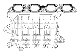
Install a new gasket to the intake manifold.
-
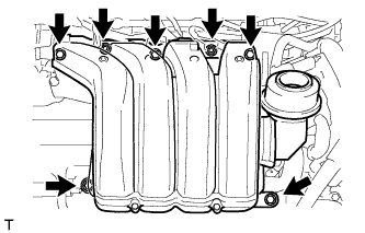
Install the intake manifold and intake manifold stay with the 5 bolts and 2 nuts.
- Torque:
- 28 N*m { 286 kgf*cm, 21 ft.*lbf }
-
Connect the fuel vapor feed hose and ventilation hose.
-
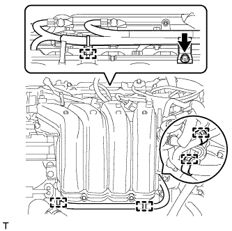
Attach the 5 clamps to the intake manifold.
-
Install the wire harness clamp bracket with the bolt.
- Torque:
- 10 N*m { 102 kgf*cm, 7 ft.*lbf }
-
-
INSTALL THROTTLE BODY ASSEMBLY
-
Install a new gasket to the intake manifold.
-
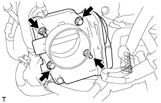
Install the throttle body with the 2 bolts and 2 nuts.
- Torque:
- 10 N*m { 102 kgf*cm, 7 ft.*lbf }
-
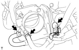
Connect the throttle body connector and 2 water hoses.
-