CYLINDER BLOCK DISASSEMBLY

-
INSPECT CONNECTING ROD THRUST CLEARANCE
-
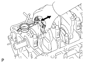
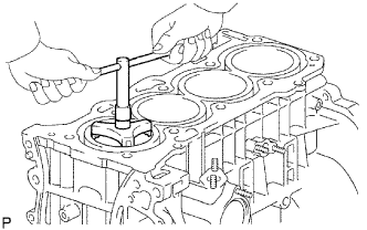
Using a dial indicator, measure the thrust clearance while moving the connecting rod back and forth.
Standard thrust clearance 0.160 to 0.362 mm (0.00630 to 0.0143 in.) Maximum thrust clearance 0.362 mm (0.0143 in.) If the thrust clearance is more than the maximum, replace the connecting rod. If necessary, replace the crankshaft.
-
-
INSPECT CONNECTING ROD OIL CLEARANCE
Note
Do not turn the crankshaft during the measurement.
-
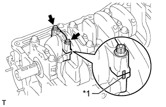
Text in Illustration *1 Matchmark Check that the matchmarks on the connecting rod and cap are aligned to ensure correct reassembly.
Tech Tips
The matchmarks on the connecting rods and caps are for ensuring correct reassembly.
-
Using a 12 mm socket wrench, remove the 2 bolts and connecting rod cap.
-
Clean the crank pin and bearing.
-
Check the crank pin and bearing for pitting and scratches.
-
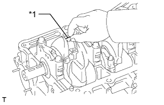
Text in Illustration *1 Plastigage Lay a strip of Plastigage on the crank pin.
-
Align the bearing claw with the oil groove of the connecting rod cap and install the bearing.
-
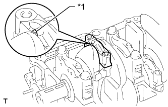
Text in Illustration *1 Front Mark Check that the front mark of the connecting rod cap is facing in the correct direction and install the cap.
-
Apply a light coat of engine oil to the threads and under the heads of the connecting rod cap bolts.
-
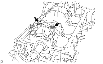
Using a 12 mm socket wrench, tighten the bolts in several passes to the specified torque.
- Torque:
- 25 N*m { 250 kgf*cm, 18 ft.*lbf }
-
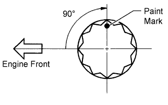
Mark the front of the connecting rod bolts with paint.
-
Tighten the rod bolts 90° as shown in the illustration.
-
Check that the crankshaft turns smoothly.
-
Using a 12 mm socket wrench, remove the 2 bolts and connecting rod cap.
-
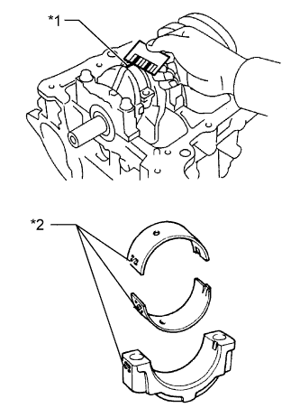
Text in Illustration *1 Plastigage *2 Diameter Mark Measure the Plastigage at its widest point.
Standard oil clearance 0.024 to 0.048 mm (0.000945 to 0.00189 in.) Maximum oil clearance 0.08 mm (0.00315 in.) Note
Remove the Plastigage completely after the measurement.
If the oil clearance is more than the maximum, replace the connecting rod bearing. If necessary, grind or replace the crankshaft.
Tech Tips
If replacing a bearing, select a new one with the same number as marked on the connecting rod. There are 3 sizes of standard bearings, marked "1", "2" and "3" accordingly.
Standard Connecting Rod Large End Bore Diameter Mark Specified Condition Mark 1 51.000 to 51.007 mm (2.00787 to 2.00815 in.) Mark 2 51.008 to 51.013 mm (2.00818 to 2.00838 in.) Mark 3 51.014 to 51.020 mm (2.00842 to 2.00866 in.) Standard Connecting Rod Bearing Thickness Mark Specified Condition Mark 1 1.485 to 1.488 mm (0.05846 to 0.05858 in.) Mark 2 1.489 to 1.491 mm (0.05862 to 0.05870 in.) Mark 3 1.492 to 1.494 mm (0.05874 to 0.05882 in.) Standard crankshaft pin diameter 47.990 to 48.000 (1.8894 to 1.8898 in.)
-
-
REMOVE PISTON WITH CONNECTING ROD
-
Using a ridge reamer, remove all the carbon from the top of the cylinder.
-
Push the piston, connecting rod assembly and upper bearing through the top of the cylinder block.
Tech Tips
-
Keep the bearing, connecting rod and cap together.
-
Arrange the piston and connecting rod assemblies in the correct order.
-
-
-
REMOVE CONNECTING ROD BEARING
-
Remove the connecting rod bearings from the connecting rods and connecting rod caps.
Tech Tips
Arrange the removed parts in the correct order.
-
-
REMOVE PISTON RING SET
-
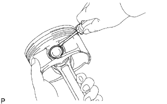
Using a piston ring expander, remove the 2 compression rings.
-
Remove the 2 side rails and expander by hand.
Tech Tips
Arrange the removed parts in the correct order.
-
-
REMOVE PISTON WITH PIN SUB-ASSEMBLY
-
Disconnect the connecting rod from the piston.
-
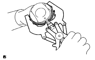
Using a small screwdriver, pry out the 2 snap rings.
-
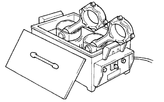
Gradually heat the piston to 80 to 90°C (176 to 194°F).
-
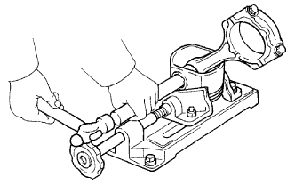
Using a hammer and brass bar, lightly tap out the piston pin, and then remove the connecting rod.
Tech Tips
-
The piston and pin are a matched set.
-
Arrange the piston, pin, rings, connecting rod and bearings in the correct order.
-
-
-
Clean the piston.
-
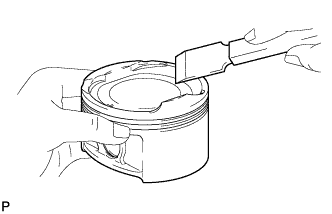
Using a gasket scraper, remove the carbon from the piston top.
-
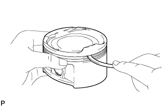
Using a groove cleaning tool or a broken ring, clean the piston ring grooves.
-
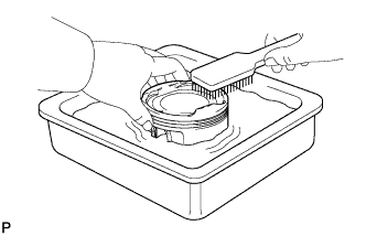
Using a brush and solvent, thoroughly clean the piston.
Note
Do not use a wire brush.
-
-
-
INSPECT CRANKSHAFT THRUST CLEARANCE
-
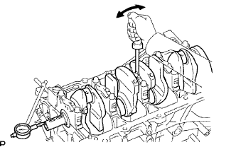
Using a dial indicator, measure the thrust clearance while prying the crankshaft back and forth with a screwdriver.
Standard thrust clearance 0.04 to 0.24 mm (0.00157 to 0.00945 in.) Maximum thrust clearance 0.30 mm (0.0118 in.) If the thrust clearance is more than the maximum, replace the thrust washers as a set.
Tech Tips
The thrust washer thickness is 1.930 to 1.980 mm (0.0760 to 0.0780 in.).
-
-
REMOVE CRANKSHAFT
-
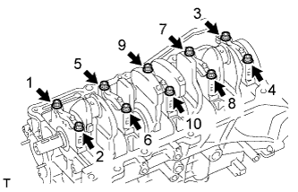
Using several steps, uniformly loosen and remove the 10 bearing cap bolts in the sequence shown in the illustration.
-
Remove the 5 bearing caps from the cylinder block.
-
Remove the crankshaft from the cylinder block.
-
-
REMOVE CRANKSHAFT THRUST WASHER UPPER
-
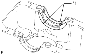
Text in Illustration *1 Oil Groove Remove the upper thrust washers from the cylinder block.
-
-
REMOVE CRANKSHAFT BEARING
-
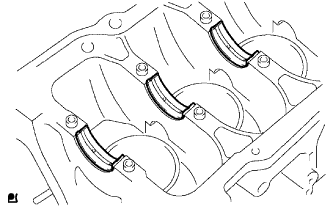
Remove the 5 crankshaft bearings from the cylinder block.
Tech Tips
Arrange the bearings in the correct order.
-
-
REMOVE NO. 2 CRANKSHAFT BEARING
-
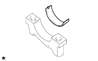
Remove the 5 No. 2 crankshaft bearings from the 5 crankshaft bearing caps.
Tech Tips
Arrange the bearings in the correct order.
-
-
REMOVE STUD BOLT
Note
If a stud bolt is deformed or its threads are damaged, replace it.