ENGINE UNIT DISASSEMBLY

-
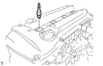
REMOVE SPARK PLUG
-
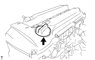
REMOVE OIL FILLER CAP SUB-ASSEMBLY
-
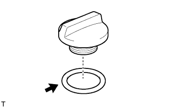
REMOVE OIL FILLER CAP GASKET
-
REMOVE CAMSHAFT POSITION SENSOR
-
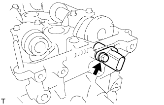
Remove the bolt and camshaft position sensor.
-
-
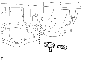
REMOVE CRANKSHAFT POSITION SENSOR
-
Disconnect the wire harness clamp.
-
Disconnect the wire harness from the wire harness clamp bracket.
-
Remove the 2 bolts and sensor.
-
-
REMOVE V-RIBBED BELT TENSIONER ASSEMBLY
-
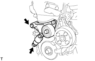
Remove the bolt, nut and V-ribbed belt tensioner.
-
-
REMOVE VENTILATION VALVE SUB-ASSEMBLY
-
Using a 22 mm deep socket wrench, remove the ventilation valve from the cylinder head cover.
-
-
REMOVE CYLINDER HEAD COVER SUB-ASSEMBLY
-
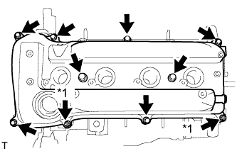
Text in Illustration *1 Nut Remove the 8 bolts, 2 nuts, cylinder head cover and gasket.
-
-
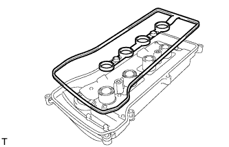
REMOVE CYLINDER HEAD COVER GASKET
-
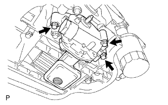
REMOVE OIL FILTER SUB-ASSEMBLY
-
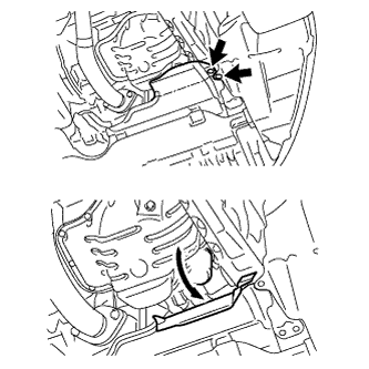
except Rough Road Area Specification Vehicles:
Detach the 2 clips and open the engine under cover as shown in the illustration.
-

Using SST, remove the oil filter.
- SST
- 09228-06501
-
-
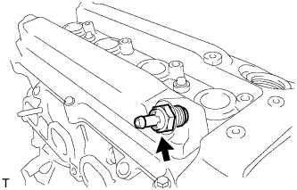
REMOVE OIL FILTER UNION
-
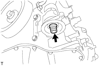
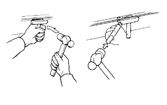
Using a 12 mm hexagon wrench, remove the oil filter union.
-
-
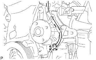
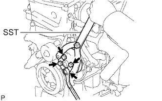
REMOVE WATER PUMP PULLEY
-
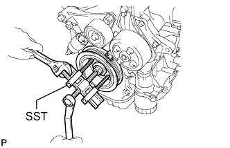
Using SST, remove the 4 bolts and water pump pulley.
- SST
- 09960-10010 ( 09962-01000, 09963-00700 )
-
-
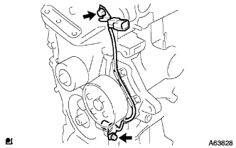
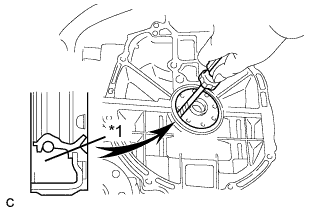
REMOVE WATER PUMP ASSEMBLY

-
Disconnect the clamp of the crankshaft position sensor from the water pump.
-
Disconnect the wire of the crankshaft position sensor from the clamp bracket.
Text in Illustration *1 Bracket -
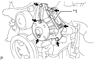
Text in Illustration *1 Bracket Remove the 4 bolts, 2 nuts and clamp bracket.
-
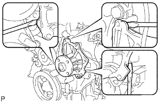
Using a screwdriver, pry between the water pump and cylinder block, and then remove the water pump.
Tech Tips
Tape the screwdriver tip before use.
Note
Be careful not to damage the contact surfaces of the water pump and cylinder block.
-
-
REMOVE OIL PAN DRAIN PLUG
-
Remove the drain plug and gasket.
-
-
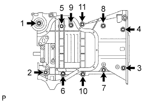
REMOVE OIL PAN SUB-ASSEMBLY
-
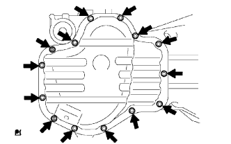
Remove the 12 bolts and 2 nuts.
-
Insert the blade of an oil pan seal cutter between the crankcase, chain cover and oil pan, and cut off the applied sealer and remove the oil pan.
Note
Be careful not to damage the contact surface of the crankcase, chain cover and oil pan.
-
-
REMOVE CRANKSHAFT PULLEY
-

Using SST, loosen the crankshaft pulley bolt.
- SST
- 09213-54015 ( 91651-60855 )
- 09330-00021
-
Further loosen the pulley bolt until 2 or 3 threads are engaged with the crankshaft.
-
Using the pulley bolt and SST, remove the crankshaft pulley.
- SST
- 09950-50013 ( 09951-05010, 09952-05010, 09953-05020, 09954-05021, 09957-04010 )
Tech Tips
If necessary, remove the pulley and pulley bolt using SST.
-
-
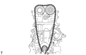
SET NO. 1 CYLINDER TO TDC/COMPRESSION
-
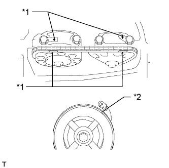
Text in Illustration *1 Timing Mark *2 Groove Turn the crankshaft pulley until the groove and the timing mark "0" on the timing chain cover are aligned.
-
Check that each timing mark on the camshaft timing gear and sprocket is aligned with the timing marks located on the No. 1 and No. 2 bearing caps as shown in the illustration.
If not, turn the crankshaft 1 revolution (360°) to align the timing marks as above.
-
-
REMOVE NO. 1 CHAIN TENSIONER ASSEMBLY
-
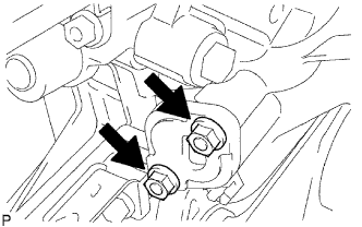
Remove the 2 nuts, chain tensioner and gasket.
Note
Do not turn the crankshaft without the chain tensioner.
-
-
REMOVE TIMING CHAIN COVER SUB-ASSEMBLY
-
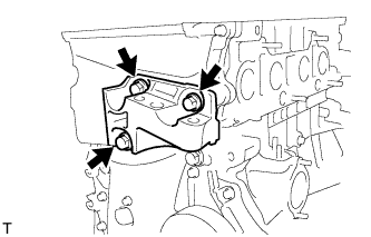
Remove the 3 bolts and engine mounting bracket RH.
-
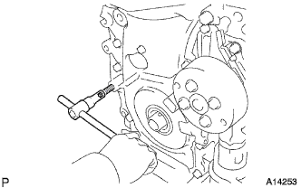
Using an E10 "TORX" socket, remove the stud bolt for the V-ribbed belt tensioner.
-
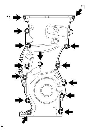
Text in Illustration *1 Nut Remove the 12 bolts and 2 nuts.
-
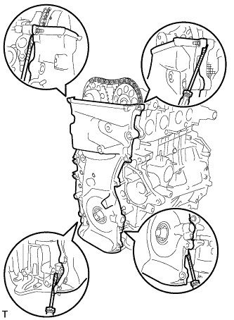
Remove the timing chain cover by prying the areas between the timing chain cover, cylinder head and cylinder block with a screwdriver.
Tech Tips
Tape the screwdriver tip before use.
Note
Be careful not to damage the contact surfaces of the timing chain cover, cylinder head and cylinder block.
-
-
REMOVE TIMING CHAIN COVER OIL SEAL
-

Place the timing chain cover on wooden blocks.
-
Using a screwdriver, pry out the oil seal.
Tech Tips
Tape the screwdriver tip before use.
Note
Do not damage the surface of the oil seal press fit hole.
-
-
REMOVE NO. 1 CRANKSHAFT POSITION SENSOR PLATE
-
REMOVE TIMING CHAIN GUIDE
-
Remove the bolt and timing chain guide.
-
-
REMOVE CHAIN TENSIONER SLIPPER
-
Remove the bolt and chain tensioner slipper.
-
-
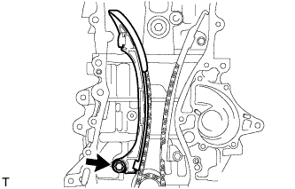
REMOVE NO. 1 CHAIN VIBRATION DAMPER
-

Remove the 2 bolts and chain vibration damper.
-
-
REMOVE CHAIN SUB-ASSEMBLY
-
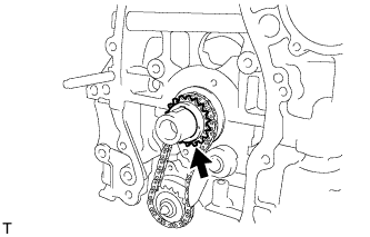
REMOVE CRANKSHAFT TIMING SPROCKET
-
REMOVE NO. 2 CHAIN SUB-ASSEMBLY
-
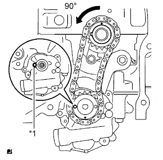
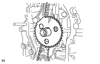
Text in Illustration *1 Groove Turn the crankshaft 90° counterclockwise to align the adjusting hole of the oil pump drive shaft sprocket with the groove of the oil pump.
-
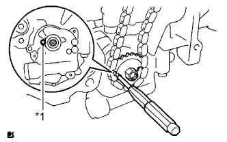
Text in Illustration *1 Groove Insert a 4 mm diameter bar into the adjusting hole of the oil pump drive shaft sprocket to lock the gear in position, and then remove the nut.
-

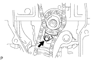
Text in Illustration *1 Bolt *2 Chain Tensioner Plate *3 Spring Remove the bolt, chain tensioner plate and spring.
-
Remove the oil pump drive sprocket, oil pump drive shaft sprocket and No. 2 chain.
-
-
REMOVE KEY
-
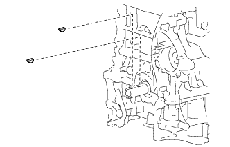
Remove the 2 keys from the crankshaft.
-
-
REMOVE OIL PUMP ASSEMBLY
-
Remove the 3 bolts, oil pump and gasket.
-
-
REMOVE NO. 2 CAMSHAFT
-
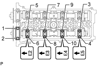
Using several steps, uniformly loosen and remove the 10 bearing cap bolts in the sequence shown in the illustration.
Tech Tips
Arrange the removed parts in the correct order.
Note
Uniformly loosen the bolts while keeping the camshaft level.
-
Remove the 5 bearing caps.
-
Remove the No. 2 camshaft.
-
-
REMOVE CAMSHAFT
-
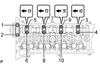
Using several steps, uniformly loosen and remove the 10 bearing cap bolts in the sequence shown in the illustration.
Tech Tips
Arrange the removed parts in the correct order.
Note
Uniformly loosen the bolts while keeping the camshaft level.
-
Remove the 5 bearing caps.
-
Remove the camshaft.
-
-
REMOVE NO. 2 CAMSHAFT BEARING
-
Remove the No. 2 camshaft bearing from the cylinder head.
-
-
REMOVE NO. 1 CAMSHAFT BEARING
-
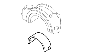
Remove the camshaft bearing from the No. 1 camshaft bearing cap.
-
-
REMOVE CYLINDER HEAD SUB-ASSEMBLY
-
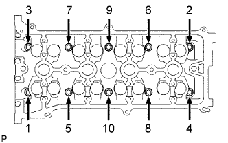
Using several steps, uniformly loosen and remove the 10 cylinder head bolts and 10 plate washers with a 10 mm bi-hexagon wrench in the sequence shown in the illustration.
Note
Head warpage or cracking could result from removing the bolts in the wrong order.
-
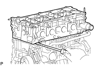
Using a screwdriver with its tip wrapped with tape, pry between the cylinder head and cylinder block, and remove the cylinder head.
Note
Be careful not to damage the contact surfaces of the cylinder head and cylinder block.
-
-
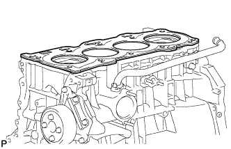
REMOVE CYLINDER HEAD GASKET
-
REMOVE CYLINDER BLOCK WATER DRAIN COCK SUB-ASSEMBLY
-
Remove the water drain cock from the stiffening crankcase.
-
Remove the water drain cock plug from the water drain cock.
-
-
REMOVE NO. 3 CYLINDER BLOCK STRAIGHT SCREW PLUG WITH HEAD
-
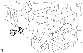
Using an 8 mm socket hexagon wrench, remove the plug and gasket.
-
-
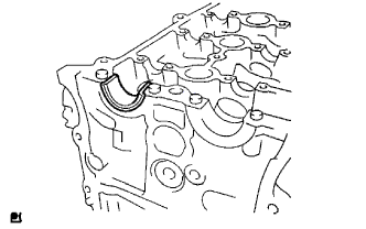
REMOVE ENGINE REAR OIL SEAL
-
Text in Illustration *1 Cut Position Using a knife, cut off the lip of the oil seal.
-
Using a screwdriver, pry out the oil seal.
Tech Tips
Tape the screwdriver tip before use.
Note
After removing, check the crankshaft for damage. If damaged, smooth the surface with 400-grit sandpaper.
-
-
REMOVE STIFFENING CRANKCASE ASSEMBLY
-
Using several steps, uniformly loosen and remove the 11 bolts in the sequence shown in the illustration.
-

Remove the crankcase by prying the areas between the crankcase and cylinder block.
Note
Be careful not to damage the contact surfaces of the crankcase and cylinder block.
-
Remove the O-ring from the cylinder block.
-