ENGINE ASSEMBLY REMOVAL

-
DISCHARGE FUEL SYSTEM PRESSURE
-
Discharge fuel system pressure Click here.
-
-
REMOVE FRONT WIPER MOTOR AND LINK ASSEMBLY
-
Remove the front wiper motor and link Click here.
-
-
PLACE FRONT WHEELS FACING STRAIGHT AHEAD
-
SECURE STEERING WHEEL
-
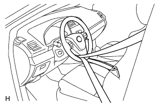
Secure the steering wheel with the seat belt in order to prevent rotation.
Tech Tips
This operation is useful to prevent damage to the spiral cable.
-
-
REMOVE ENGINE ROOM SIDE COVER
-
Remove the clip and engine room side cover.
-
-
DISCONNECT CABLE FROM NEGATIVE BATTERY TERMINAL
-
Loosen the nut and disconnect the cable.
Note
When disconnecting the cable, some systems need to be initialized after the cable is reconnected Click here.
-
-
DISCONNECT CABLE FROM POSITIVE BATTERY TERMINAL
-
Loosen the nut and disconnect the cable.
-
-
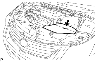
REMOVE RADIATOR SUPPORT OPENING COVER
-
Remove the 8 clips and radiator support opening cover.
-
-
RECOVER REFRIGERANT FROM REFRIGERATION SYSTEM
-
Start the engine.
-
Turn the A/C switch on.
-
Operate the cooler compressor while the engine speed is approximately 1000 rpm for 5 to 6 minutes to circulate the refrigerant and collect the compressor oil remaining in each component into the cooler compressor.
-
Stop the engine.
-
Recover the refrigerant from the A/C system using a refrigerant recovery unit.
-
-
REMOVE BATTERY CLAMP SUB-ASSEMBLY
-
Remove the bolt and loosen the nut.
-
Detach the hook of the battery clamp from the battery carrier, and then remove the battery clamp.
-
-
REMOVE BATTERY
-
REMOVE BATTERY TRAY
-
REMOVE BATTERY CARRIER
-
Disconnect the 2 wire harness protector clamps.
-
Remove the 4 bolts and battery carrier.
-
-
REMOVE FRONT WHEELS
-
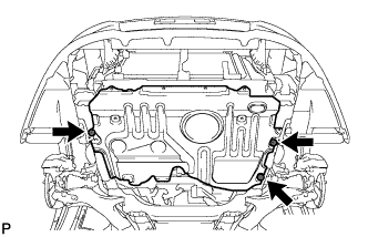
REMOVE FRONT LOWER BUMPER ABSORBER
-
Remove the 4 screws and 2 bolts.
Tech Tips
Pull down the fender liner so that the front lower bumper absorber can be removed in the next step.
-
Remove the 3 screws, 8 bolts and front lower bumper absorber.
-
-
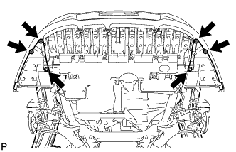
REMOVE NO. 1 ENGINE UNDER COVER
-
Remove the 5 clips and under cover.
-
-
REMOVE NO. 1 ENGINE UNDER COVER (for Rough Road Area Specification Vehicles)
-
Remove the 3 bolts and under cover.
-
-
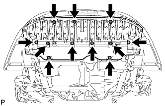
REMOVE CENTER NO. 4 ENGINE UNDER COVER
-
Remove the 5 clips and under cover.
-
-
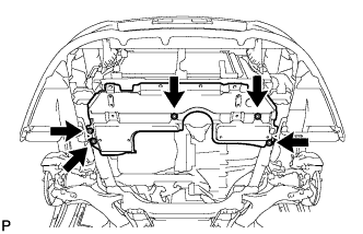
REMOVE REAR ENGINE UNDER COVER RH
-
Remove the 5 clips and under cover.
-
-
REMOVE NO. 1 ENGINE COVER SUB-ASSEMBLY
-
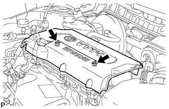
Remove the 2 nuts and engine cover.
-
-
DRAIN ENGINE OIL
-
Remove the oil filler cap.
-
Remove the oil pan drain plug and drain the oil into a container.
-
Clean and install the oil pan drain plug with a new gasket.
- Torque:
- 40 N*m { 408 kgf*cm, 30 ft.*lbf }
-
-
DRAIN ENGINE COOLANT
Tech Tips
Collect the coolant in a container and dispose of it according to the regulations in your area.
CAUTION:
Do not remove the radiator cap while the engine and radiator are still hot. Pressurized, hot engine coolant and steam may be released and cause serious burns.
-
Loosen the radiator drain cock plug.
-
Remove the radiator cap. Then drain the coolant from the radiator.
-
Loosen the cylinder block drain cock plug. Then drain the coolant from the engine.
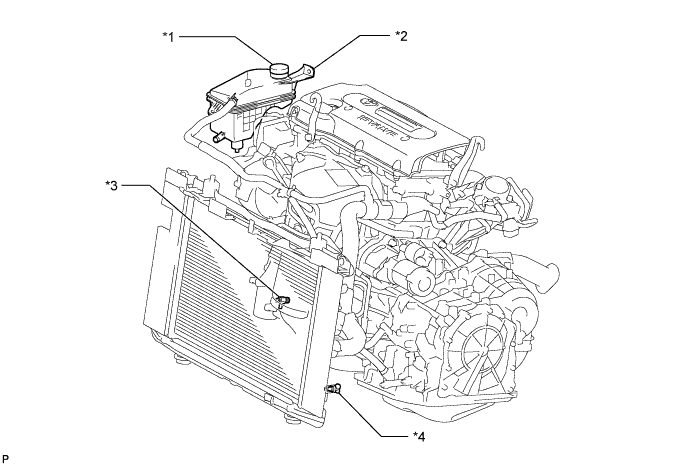
Text in Illustration *1 Radiator Reservoir Cap *3 Cylinder Block Drain Cock Plug *2 Radiator Reservoir *4 Radiator Drain Cock Plug -
Tighten the radiator drain cock plug by hand.
-
Tighten the cylinder block drain cock plug.
- Torque:
- 13 N*m { 130 kgf*cm, 9 ft.*lbf }
-
-
DISCONNECT RADIATOR RESERVOIR
-
Remove the 2 bolts and disconnect the radiator reservoir.
-
-
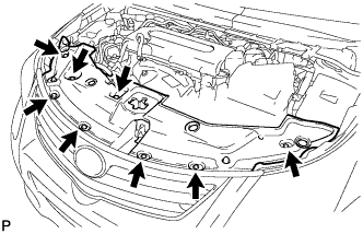
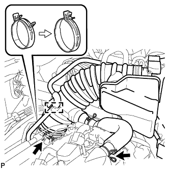
REMOVE AIR CLEANER CAP AND HOSE
-
Disconnect the mass air flow meter connector and wire harness.
-
Disconnect the purge VSV.
-
Disconnect the No. 2 ventilation hose from the cylinder head cover.
-
Disconnect the No. 2 fuel vapor feed hose from the air cleaner hose.
-
Squeeze the tabs of the No. 1 air cleaner hose clamp, and then disconnect the No. 1 air cleaner hose from the throttle body.
-
Unfasten the 3 hook clamps, and then remove the air cleaner cap and hose.
-
-
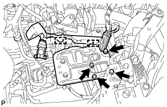
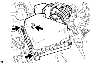
REMOVE AIR CLEANER CASE
-
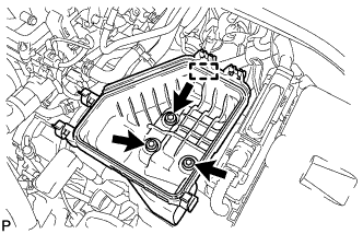
Disconnect the engine wire.
-
Remove the 3 bolts and air cleaner case.
-
-
REMOVE NO. 1 RADIATOR HOSE
-
Disconnect the No. 1 radiator hose clamp.
-
Disconnect the No. 1 radiator hose from the No. 2 water by-pass hose.
-
Remove the No. 1 radiator hose.
-
-
REMOVE NO. 2 RADIATOR HOSE
-
Remove the No. 2 radiator hose.
-
-
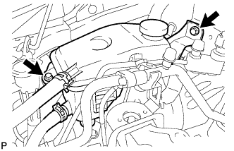
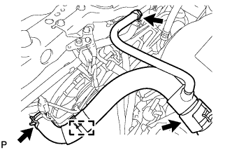
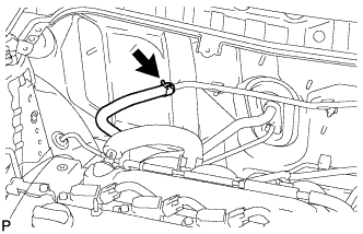
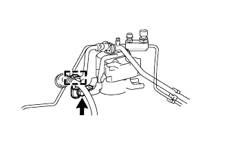
DISCONNECT OIL COOLER HOSE
-
Disconnect the 2 oil cooler hoses.
-
-
REMOVE OUTER COWL TOP PANEL SUB-ASSEMBLY
-
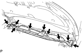
Remove the 9 bolts and outer cowl top panel.
-
-
DISCONNECT CONNECTOR TUBE HOSE
-
for LHD:
Disconnect the connector tube hose.
-
for RHD:
Disconnect the connector tube hose.
-
-
DISCONNECT HEATER WATER HOSE
-
Disconnect the breather hose.
-
Disconnect the 2 heater water hoses.
-
-
DISCONNECT FUEL TUBE
Note
Do not forcibly bend or twist the fuel main tube.
-
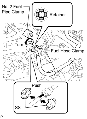
Remove the fuel tube from the fuel hose clamp.
-
Remove the fuel pipe clamp.
-
Wipe off any dirt on the fuel tube connector.
-
Hold the fuel tube connector and install SST.
- SST
- 09268-21010
-
Turn SST to align the retainer inside the fuel tube connector with the chamfered part of SST.
-
Insert SST into the fuel tube connector and hold it. Then push the fuel tube connector toward SST.
-
Mount the retainer of the fuel tube connector onto the chamfered part of SST.
-
Slide SST and the fuel tube connector together towards the fuel tube until they make a "click" sound, and then disconnect the fuel tube.
-
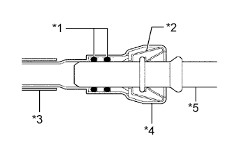
Drain the fuel remaining inside the fuel tube.
-
Cover the fuel tube and fuel pipe with a plastic bag to protect the disconnected parts.
Text in Illustration *1 O-Ring *2 Retainer *3 Nylon Tube *4 Housing *5 Pipe
-
-
DISCONNECT TRANSMISSION CONTROL CABLE ASSEMBLY
-
Remove the nut and disconnect the control cable from the control shaft lever.
-
Remove the clip and disconnect the control cable from the control cable bracket.
-
Disconnect the control cable from the control cable bracket.
-
Remove the bolt and disconnect the control cable.
-
-
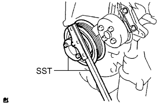
REMOVE FAN & GENERATOR V BELT
-
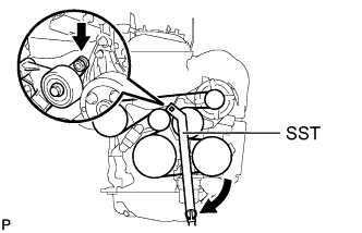
Using SST, slowly turn the V-ribbed belt tensioner clockwise.
- SST
- 09216-42010
CAUTION:
Be careful not to pinch your fingers between the parts.
Note
-
Make sure that SST and other tools are set to the tensioner securely.
-
When compressing the V-ribbed belt tension, slowly turn the tensioner.
-
Remove the belt from each pulley and slowly return the tensioner.
CAUTION:
Be careful not to pinch your fingers between the parts.
-
-
REMOVE GENERATOR ASSEMBLY
-
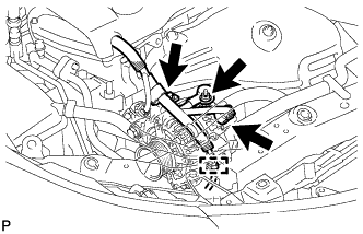
Disconnect the generator connector.
-
Open the terminal cap.
-
Remove the nut and disconnect the generator wire.
-
Remove the bolt and disconnect the wire harness clamp bracket.
-
Disconnect the wire harness clamp.
-
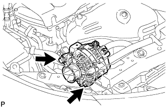
Remove the 2 bolts and generator.
-
-
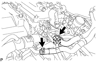
DISCONNECT DISCHARGE HOSE SUB-ASSEMBLY
-
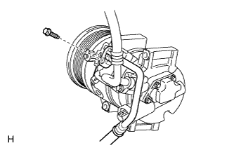
Remove the bolt and disconnect the discharge hose sub-assembly from the compressor assembly with pulley.
Note
Seal the openings of the disconnected parts using vinyl tape to prevent entry of moisture and foreign matter.
-
Remove the O-ring from the discharge hose sub-assembly.
Note
Seal the openings of the disconnected parts using vinyl tape to prevent entry of moisture and foreign matter.
-
-
DISCONNECT SUCTION HOSE SUB-ASSEMBLY
-
Remove the bolt and disconnect the suction hose sub-assembly from the compressor assembly with pulley.
Note
Seal the openings of the disconnected parts using vinyl tape to prevent entry of moisture and foreign matter.
-
Remove the O-ring from the suction hose sub-assembly.
Note
Seal the openings of the disconnected parts using vinyl tape to prevent entry of moisture and foreign matter.
-
-
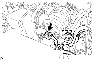
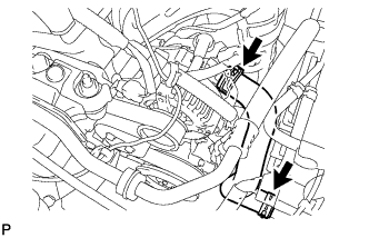
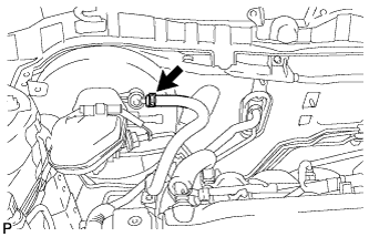
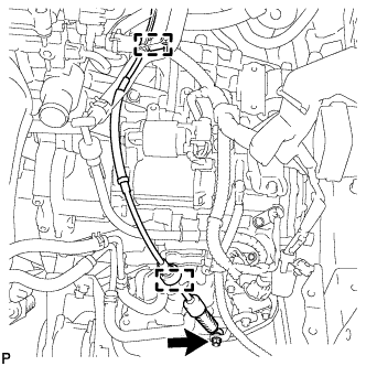
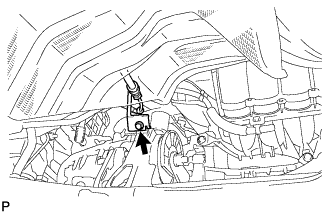
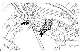
DISCONNECT ENGINE WIRE
-
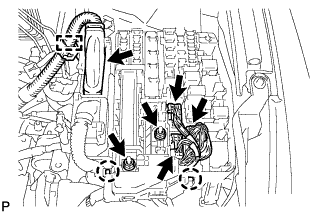
Disconnect the 3 connectors from the engine room relay block.
-
Remove the 2 nuts and disconnect the wire harnesses from the engine room relay block.
-
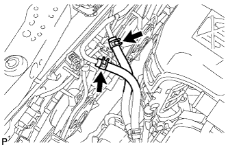
Using a screwdriver, unlock the 2 claws.
-
Pull the engine wire upward.
-
Disconnect the clamp and ECM connector Click here.
-
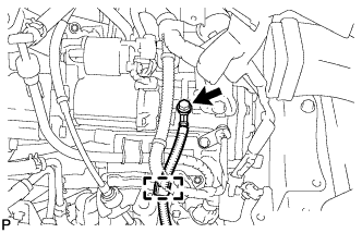
Remove the bolt and disconnect the ground cable and clamp.
-
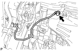
Remove the bolt and disconnect the ground cable and 2 clamps.
-
-
REMOVE FRONT EXHAUST PIPE ASSEMBLY
-
Remove the front exhaust pipe Click here.
-
-
REMOVE FRONT DRIVE SHAFT ASSEMBLY
-
Remove the front drive shaft Click here.
-
-
REMOVE COLUMN HOLE COVER SILENCER SHEET
-
Fold back the floor carpet, and then remove the 2 clips and then column hole cover silencer sheet.
-
-
DISCONNECT NO. 2 STEERING INTERMEDIATE SHAFT ASSEMBLY
-
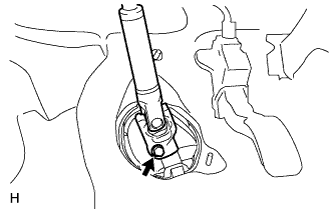
Remove the bolt.
Note
Do not disconnect the No. 2 steering intermediate shaft assembly from the steering intermediate shaft.
-
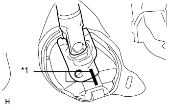
Text in Illustration *1 Matchmark Put matchmarks on the No. 2 steering intermediate shaft assembly and steering intermediate shaft.
-
Disconnect the No. 2 steering intermediate shaft assembly from the steering intermediate shaft.
-
-
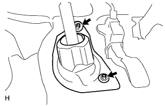
DISCONNECT NO. 1 STEERING COLUMN HOLE COVER SUB-ASSEMBLY
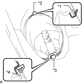
-
Remove clip A and the No. 1 steering column hole cover and detach clip B from the body.
Note
Do not damage clip A or B.
Text in Illustration *1 Lip *2 Clip B *3 Clip A *4 Lip
-
-
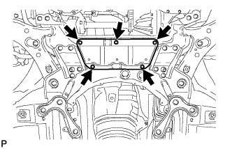
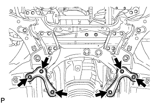
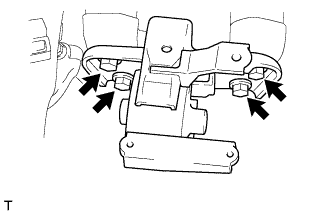
REMOVE FRONT SUSPENSION MEMBER REINFORCEMENT
-
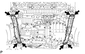
Remove the 8 bolts and 2 front suspension member reinforcements.
-
-
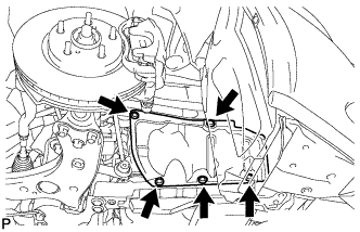
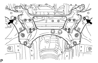
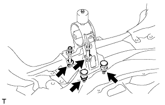
REMOVE FRONT CROSSMEMBER SUB-ASSEMBLY
-
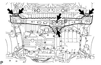
Remove the 6 bolts and front crossmember.
-
-
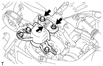
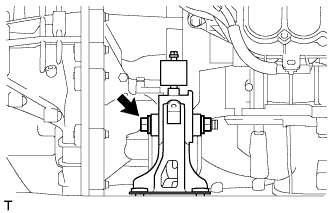
REMOVE FRONT ENGINE MOUNTING INSULATOR
-
Remove the through bolt, nut and engine mounting insulator.
-
-
REMOVE ENGINE ASSEMBLY WITH TRANSAXLE
-
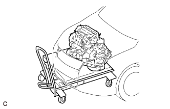
Set the engine assembly with transaxle on an engine lifter.
Tech Tips
Place the engine on wooden blocks or equivalent so that the engine is level.
-
Disconnect the air conditioning tube.
-
Remove the bolt and cooler bracket.
-
Disconnect the 2 air conditioning tubes.
-
Remove the bolt, nut and cooler bracket.
-
Remove the bolt and 2 nuts, and disconnect the engine mounting insulator RH.
-
Remove the through bolt and nut, and disconnect the engine mounting insulator LH.
-
Remove the 6 bolts and 2 front suspension member brace rears.
-
Remove the 2 bolts and front suspension crossmember.
-
Operate the engine lifter and slowly remove the engine from the vehicle.
Note
-
Make sure that the engine is clear of all wiring and hoses.
-
While lowering the engine from the vehicle, do not allow it to contact the vehicle.
-
-
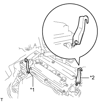
Text in Illustration *1 No. 1 Engine Hanger *2 No. 2 Engine Hanger Install the No. 1 and No. 2 engine hangers with bolts as shown in the illustration.
- Torque:
- 38 N*m { 387 kgf*cm, 28 ft.*lbf }
Tech Tips
Item Part No. No. 1 engine hanger 12281-28010, 12281-0H010 No. 2 engine hanger 12282-28010, 12282-0H010 Bolt 91552-81020 -
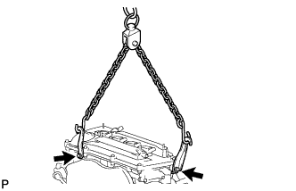
Attach an engine sling device and hang the engine with a chain block.
-
-
REMOVE DRIVE SHAFT BEARING BRACKET
-
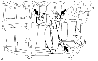
Remove the 3 bolts and bracket.
-
-
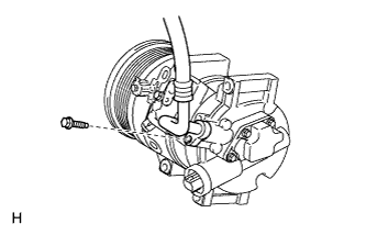
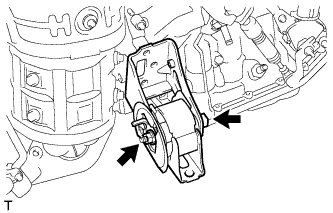
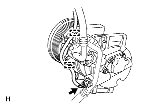
REMOVE COMPRESSOR ASSEMBLY WITH PULLEY
-
Detach the 2 clamps.
-
Disconnect the connector.
-
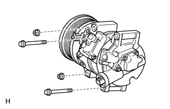
Remove the 2 bolts and 2 nuts.
-
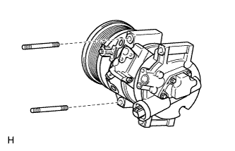
Using a "TORX" socket wrench (E8), remove the 2 stud bolts and the compressor assembly with pulley.
-
-
REMOVE STARTER ASSEMBLY
-
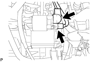
Disconnect the starter connector.
-
Open the terminal cap, remove the nut and disconnect the starter wire.
-
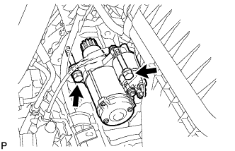
Remove the 2 bolts and starter.
-
-
REMOVE AUTOMATIC TRANSAXLE ASSEMBLY
-
Remove the automatic transaxle Click here.
-
-
REMOVE DRIVE PLATE AND RING GEAR SUB-ASSEMBLY
-
Using SST, hold the crankshaft.
- SST
- 09213-54015 ( 91651-60855 )
- 09330-00021
-
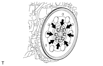
Remove the 8 bolts, rear drive plate spacer, drive plate and front drive plate spacer.
-
-
REMOVE ENGINE WIRE
-
Remove the engine wire from the engine.
-
-
INSTALL ENGINE ON ENGINE STAND
-
Install the engine to an engine stand with bolts.
-
Remove the 2 bolts and No. 1 and No. 2 engine hangers.
-
-
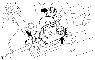
REMOVE FRONT SUSPENSION CROSSMEMBER SUB-ASSEMBLY
-
Remove the bolt and front suspension crossmember from the engine.
-
-
REMOVE REAR ENGINE MOUNTING INSULATOR
Tech Tips
Perform this procedure only when replacement of the engine mounting insulator is necessary.
-
Remove the 2 nuts, 2 bolts and engine mounting insulator.
-
-
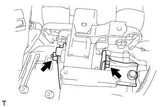
REMOVE ENGINE MOUNTING INSULATOR LH
Tech Tips
Perform this procedure only when replacement of the engine mounting insulator is necessary.
-
Remove the 4 bolts and engine mounting insulator.
-
-
REMOVE ENGINE MOUNTING INSULATOR RH
Tech Tips
Perform this procedure only when replacement of the engine mounting insulator is necessary.
-
Remove the 3 bolts and engine mounting insulator sub-assembly.
-