CYLINDER HEAD GASKET INSTALLATION

-
INSTALL CYLINDER HEAD GASKET
-
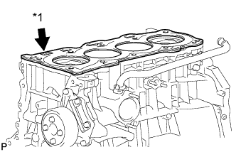
Text in Illustration *1 Lot No. Place a new gasket on the cylinder block surface with the Lot No. stamp facing upward.
Note
-
Remove any oil from the contact surface.
-
Be careful of the installation direction.
-
-
-
INSTALL CYLINDER HEAD SUB-ASSEMBLY
-
Place the cylinder head on the head gasket.
Note
Place the cylinder head gently in order to avoid damaging the gasket.
-
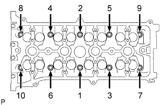
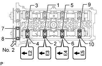
Install the cylinder head bolts.
Note
The cylinder head bolts are tightened in 2 successive steps.
-
Apply a light coat of engine oil to the threads and under the heads of the cylinder head bolts.
-
Using several steps, uniformly install and tighten the 10 cylinder head bolts and plate washers with a 10 mm bi-hexagon wrench in the order shown in the illustration.
- Torque:
- 79 N*m { 800 kgf*cm, 58 ft.*lbf }
-
-
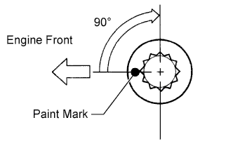
Mark the front of the cylinder head bolts with paint.
-
Tighten the cylinder head bolts 90° as shown in the illustration.
-
Check that the paint mark is now at a 90° angle to the front.
-
-
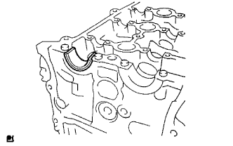
INSTALL NO. 1 CAMSHAFT BEARING
-
Clean the installation surfaces and the inner and outer surfaces of the bearing.
Note
Do not apply engine oil to the bearing or its contact surfaces.
-
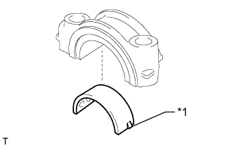
Text in Illustration *1 Claw Align the claw of the No. 1 camshaft bearing and the cutout of the No. 1 camshaft bearing cap and install the bearing onto the bearing cap.
-
-
INSTALL NO. 2 CAMSHAFT BEARING
-
Clean the installation surfaces and the inner and outer surfaces of the bearing.
Note
Do not apply engine oil to the bearing or its contact surfaces.
-
Install the No. 2 camshaft bearing onto the cylinder head.
-
-
INSTALL CAMSHAFT
-
Apply a light coat of engine oil to the journals of the camshaft.
-
Examine the front marks and numbers, and check that the order is as shown in the illustration. Then install the bearing caps onto the cylinder head.
-
Apply a light coat of engine oil to the threads and under the heads of the bearing cap bolts.
-
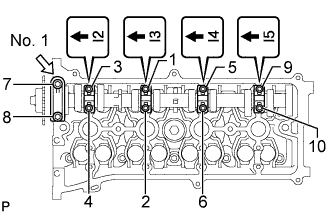
Using several steps, uniformly tighten the 10 bearing cap bolts in the sequence shown in the illustration.
- Torque:
- for No. 1 bearing cap
- 30 N*m { 301 kgf*cm, 22 ft.*lbf }
- for No. 3 bearing cap
- 9.0 N*m { 92 kgf*cm, 80 in.*lbf }
-
-
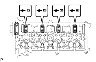
INSTALL NO. 2 CAMSHAFT
-
Apply a light coat of engine oil to the journals of the No. 2 camshaft.
-
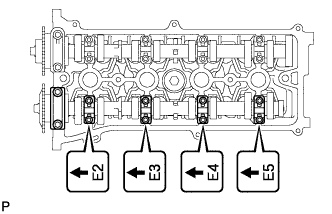
Examine the front marks and numbers, and check that the order is as shown in the illustration. Then install the bearing caps onto the cylinder head.
-
Apply a light coat of engine oil to the threads and under the heads of the bearing cap bolts.
-
Using several steps, uniformly tighten the 10 bearing cap bolts in the sequence shown in the illustration.
- Torque:
- for No. 2 bearing cap
- 30 N*m { 301 kgf*cm, 22 ft.*lbf }
- for No. 3 bearing cap
- 9.0 N*m { 92 kgf*cm, 80 in.*lbf }
-
-
CONNECT ENGINE WIRE
-
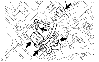
Connect the ground cable with the bolt.
- Torque:
- 8.4 N*m { 86 kgf*cm, 74 in.*lbf }
-
Connect the camshaft position sensor connector.
-
Connect the engine coolant temperature sensor connector.
-
Connect the engine oil pressure switch connector.
-
Connect the radio setting condenser connector.
-
-
INSTALL CHAIN SUB-ASSEMBLY
-
Install the chain Click here.
-
-
INSTALL EXHAUST MANIFOLD
-
Install the exhaust manifold Click here.
-
-
INSTALL INTAKE MANIFOLD
-
Install the intake manifold Click here.
-