CYLINDER HEAD GASKET INSTALLATION

-
INSPECT NO. 1 VALVE ROCKER ARM SUB-ASSEMBLY
-
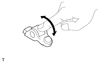
Turn the roller by hand to check that it turns smoothly.
If the roller does not turn smoothly, replace the No. 1 valve rocker arm sub-assembly.
-
-
INSPECT VALVE LASH ADJUSTER ASSEMBLY
Note
-
Keep the valve lash adjuster free from dirt and foreign matter.
-
Only use clean engine oil.
-
Place the lash adjuster into a container full of new engine oil.
-
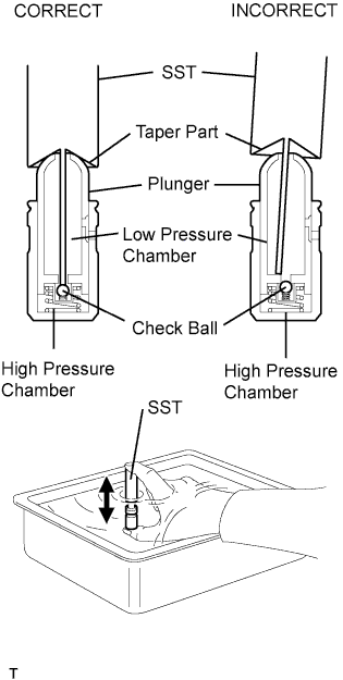
Insert the tip of SST into the lash adjuster plunger and use the tip to press down on the check ball inside the plunger.
- SST
- 09276-75010
-
Squeeze SST and the valve lash adjuster together to move the plunger up and down 5 to 6 times.
-
Check the movement of the plunger and bleed the air.
OK Plunger moves up and down. Note
When bleeding high-pressure air from the compression chamber, make sure that the tip of SST is actually pressing the check ball as shown in the illustration. If the check ball is not pressed, air bleeding is not possible.
-
After bleeding the air, remove SST. Then try to quickly and firmly press the plunger with your fingers.
OK Plunger can be pressed 3 times. If the plunger can still be compressed after pressing it 3 times, replace the valve lash adjuster with a new one.
-
-
INSPECT CYLINDER HEAD BOLT
-
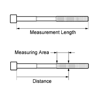
Using a vernier caliper, measure the length of the cylinder head bolt from the seat to the end.
Standard length 146.8 to 148.2 mm (5.78 to 5.83 in.) Maximum length 149.2 mm (5.87 in.) If the length is more than the maximum, replace the cylinder head bolt.
-
Using a vernier caliper, measure the diameter of the elongated thread at the measuring point.
Distance 115 mm (4.53 in.) Standard diameter 9.77 to 9.96 mm (0.385 to 0.392 in.) Minimum diameter 9.4 mm (0.370 in.) If the diameter is less than the minimum, replace the cylinder head bolt.
Tech Tips
If a visual check reveals no excessively thin areas, check the center of the bolt (refer to illustration) and find the area that has the smallest diameter.
-
-
INSPECT CYLINDER HEAD
-
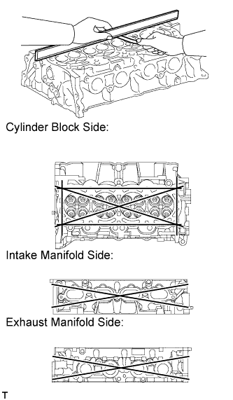
Using a precision straightedge and feeler gauge, measure the warpage of the contact surfaces where the cylinder head contacts the cylinder block and manifolds.
Maximum Warpage Item Specified Condition Cylinder block side 0.05 mm (0.00197 in.) Intake manifold side 0.10 mm (0.00394 in.) Exhaust manifold side 0.10 mm (0.00394 in.) If the warpage is more than the maximum, replace the cylinder head.
-
-
INSTALL CYLINDER HEAD GASKET
-
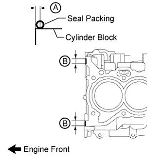
Apply seal packing to the cylinder block as shown in the illustration.
Seal packing Toyota Genuine Seal Packing Black, Three Bond 1207B or equivalent Standard seal packing diameter 4.0 mm (0.157 in.) Application Specification Area Seal Packing Application Length Distance from Edge of Cylinder Block to Center of Seal Packing A - 2.0 to 4.0 mm (0.0787 to 0.157 in.) B 10 to 15 mm (0.394 to 0.591 in.) - Note
Remove any oil from the cylinder block.
-
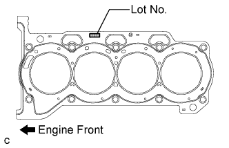
Place a new cylinder head gasket on the cylinder block with the Lot No. stamp facing upward.
Note
Install the cylinder head gasket within 3 minutes after applying seal packing.
-
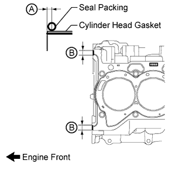
Apply seal packing to the cylinder head gasket as shown in the illustration.
Seal packing Toyota Genuine Seal Packing Black, Three Bond 1207B or equivalent Standard seal packing diameter 4.0 mm (0.157 in.) Application Specification Area Seal Packing Application Length Distance from Edge of Cylinder Head Gasket to Center of Seal Packing A - 2.0 to 4.0 mm (0.0787 to 0.157 in.) B 10 to 15 mm (0.394 to 0.591 in.) - Note
-
Remove any oil from the cylinder head gasket and cylinder head.
-
Install the cylinder head within 3 minutes and tighten the bolts within 15 minutes of applying seal packing.
-
-
-
INSTALL CYLINDER HEAD SUB-ASSEMBLY
Tech Tips
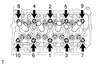
The cylinder head bolts are tightened in 3 progressive steps.
-
Place the cylinder head on the cylinder block.
Note
-
Make sure that no oil is on the mounting surface of the cylinder head.
-
Place the cylinder head on the cylinder block gently in order not to damage the gasket with the bottom part of the head.
-
-
Install the plate washers to the cylinder head bolts.
-
Apply a light coat of engine oil to the threads and under the heads of the cylinder head bolts.
-
Step 1:
-
Using a 10 mm bi-hexagon wrench, install and uniformly tighten the 10 cylinder head bolts in several steps, in the sequence shown in the illustration.
- Torque:
- 49 N*m { 500 kgf*cm, 36 ft.*lbf }
Note
Do not drop the plate washers into the cylinder head.
-
-
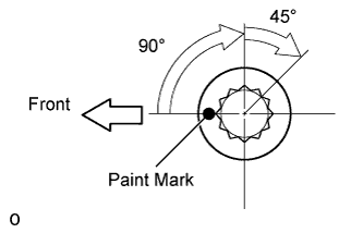
Step 2:
-
Mark each cylinder head bolt head with paint as shown in the illustration.
-
Tighten the cylinder head bolts 90° in the sequence shown in step 1.
-
-
Step 3:
-
Tighten the cylinder head bolts another 45° in the sequence shown in step 1.
-
-
Check that the paint mark is now at a 135° angle to the front.
-
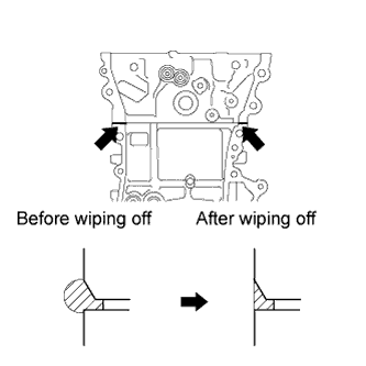
After tightening the cylinder head bolts, wipe off the seal packing material that has seeped out from between the contact surfaces of the cylinder head and cylinder block.
-
-
INSTALL VALVE STEM CAP
-
Apply a light coat of engine oil to the valve stem ends.
-
Install the 16 valve stem caps to the cylinder head.
Note
Do not drop the valve stem caps into the cylinder head.
-
-
INSTALL NO. 1 WATER BY-PASS PIPE
-
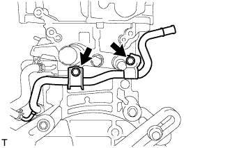
Install the water by-pass pipe with the 2 bolts.
- Torque:
- 21 N*m { 214 kgf*cm, 15 ft.*lbf }
-
-
INSTALL EXHAUST MANIFOLD
-
Install a new exhaust manifold gasket.
-
for Nut Type A:
-
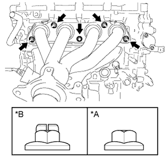
Text in Illustration *A Nut Type A *B Nut Type B Install the exhaust manifold with the 5 nuts.
- Torque:
- 21 N*m { 214 kgf*cm, 15 ft.*lbf }
-
-
for Nut Type B:
-
Install the exhaust manifold with 5 new nuts.
- Torque:
- 37 N*m { 377 kgf*cm, 27 ft.*lbf }
-
-
-
INSTALL MANIFOLD STAY
-
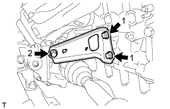
Temporarily install the manifold stay with the 3 bolts.
-
While pushing the manifold stay toward the exhaust manifold, tighten the 2 bolts labeled 1.
- Torque:
- 43 N*m { 438 kgf*cm, 32 ft.*lbf }
-
Tighten the bolt labeled 2.
- Torque:
- 43 N*m { 438 kgf*cm, 32 ft.*lbf }
-
-
INSTALL DRIVE SHAFT HEAT INSULATOR SUB-ASSEMBLY
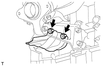
-
Install the heat insulator with the 2 nuts.
- Torque:
- 18 N*m { 179 kgf*cm, 13 ft.*lbf }
-
-
INSTALL NO. 1 EXHAUST MANIFOLD HEAT INSULATOR
-
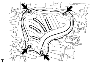
Install the heat insulator with the 4 bolts.
- Torque:
- 12 N*m { 122 kgf*cm, 9 ft.*lbf }
-
-
INSTALL CAMSHAFT HOUSING SUB-ASSEMBLY
-
Install the camshaft housing sub-assembly Click here.
-
-
INSTALL ENGINE ASSEMBLY WITH TRANSAXLE
-
Install the engine assembly with transaxle Click here.
-