CAMSHAFT INSTALLATION

-
INSTALL CAMSHAFT TIMING GEAR OR SPROCKET (for Intake Side)
-
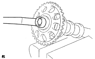
Clamp the camshaft in a vise and install the camshaft timing sprocket with the bolt.
- Torque:
- 54 N*m { 551 kgf*cm, 40 ft.*lbf }
Note
Do not damage the camshaft.
-
-
INSTALL CAMSHAFT
-
Apply a light coat of engine oil to the journals of the camshaft.
-
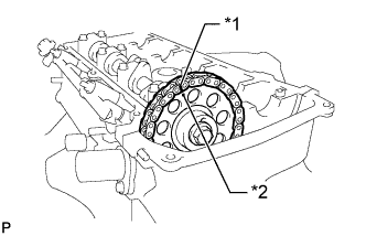
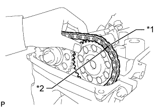
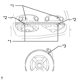
Install the timing chain onto the camshaft timing gear with the paint mark aligned with the timing mark on the camshaft timing gear as shown in the illustration.
Text in Illustration *1 Paint Mark *2 Timing Mark -
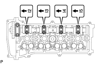
Examine the front marks and numbers, and check that the order is as shown in the illustration. Then install the bearing caps onto the cylinder head.
-
Apply a light coat of engine oil to the threads and under the heads of the bearing cap bolts.
-
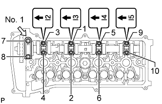
Using several steps, uniformly tighten the 10 bearing cap bolts in the sequence shown in the illustration.
- Torque:
- for No. 1 bearing cap
- 30 N*m { 301 kgf*cm, 22 ft.*lbf }
- for No. 3 bearing cap
- 9.0 N*m { 92 kgf*cm, 80 in.*lbf }
-
-
INSTALL NO. 2 CAMSHAFT
-
Apply a light coat of engine oil to the journals of the No. 2 camshaft.
-
Install the camshaft timing sprocket to the No. 2 camshaft.
-
Put the No. 2 camshaft on the cylinder head with the paint mark of the chain aligned with the timing mark on the camshaft timing sprocket.
Text in Illustration *1 Paint Mark *2 Timing Mark -
While holding the No. 2 camshaft by hand, temporarily install the camshaft timing sprocket set bolt.
-
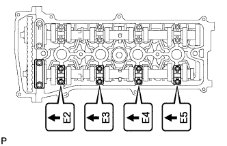
Examine the front marks and numbers, and check that the order is as shown in the illustration. Then install the bearing caps onto the cylinder head.
-
Apply a light coat of engine oil to the threads and under the heads of the bearing cap bolts.
-
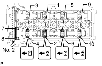
Using several steps, uniformly tighten the 10 bearing cap bolts in the sequence shown in the illustration.
- Torque:
- for No. 2 bearing cap
- 30 N*m { 301 kgf*cm, 22 ft.*lbf }
- for No. 3 bearing cap
- 9.0 N*m { 92 kgf*cm, 80 in.*lbf }
-
-
TIGHTEN CAMSHAFT TIMING GEAR OR SPROCKET (for Exhaust Side)
-
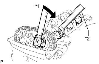
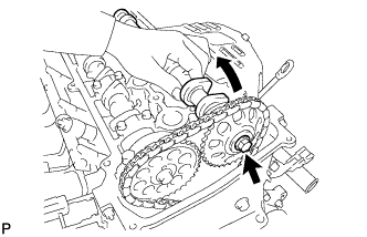
Text in Illustration *1 Tighten *2 Hold While holding the camshaft with a wrench, tighten the camshaft timing sprocket set bolt.
- Torque:
- 54 N*m { 551 kgf*cm, 40 ft.*lbf }
Note
Be careful not to damage the valve lifter.
-
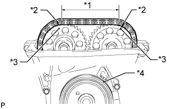
Text in Illustration *1 7 Links *2 Paint Mark *3 Timing Mark *4 Groove Check that the paint marks on the chain are aligned with the timing marks on the camshaft timing gear and camshaft timing sprocket. Also, check that the crankshaft pulley groove is aligned with the timing mark "0" on the timing mark chain cover.
-
-
INSTALL NO. 1 CHAIN TENSIONER ASSEMBLY
-
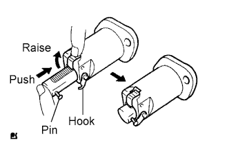
Release the ratchet pawl, fully push in the plunger, and then hook the hook to the pin so that the plunger is in the position shown in the illustration.
-
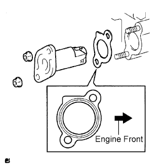
Install a new gasket and the chain tensioner with the 2 nuts.
- Torque:
- 9.0 N*m { 92 kgf*cm, 80 in.*lbf }
Note
When installing the chain tensioner, set the hook again if the hook releases the plunger.
-
-
SET NO. 1 CYLINDER TO TDC/COMPRESSION
-
Text in Illustration *1 Timing Mark *2 Paint Mark *3 Groove Turn the crankshaft pulley until the groove and the timing mark "0" on the timing chain cover are aligned.
-
Check that each timing mark on the camshaft timing gear and sprocket is aligned with each timing mark located on the No. 1 and No. 2 bearing caps as shown in the illustration.
If not, turn the crankshaft pulley 1 revolution (360°) to align the timing marks as illustrated.
-
Place paint marks on the chain in alignment with the timing marks on the camshaft timing gear and camshaft timing sprocket.
-
-
CHECK VALVE CLEARANCE
-
Check the valve clearance Click here.
-
-
INSTALL CYLINDER HEAD COVER GASKET
-
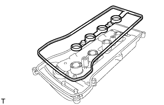
Install a new gasket onto the cylinder head cover.
-
-
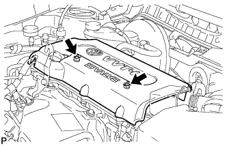
INSTALL CYLINDER HEAD COVER SUB-ASSEMBLY
-
Remove any old packing material from the contact surface.
-
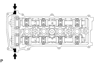
Apply seal packing to the 2 locations shown in the illustration.
Seal packing Toyota Genuine Seal Packing Black, Three Bond 1207B or Equivalent Note
-
Remove any oil from the contact surface.
-
Install the cylinder head cover within 3 minutes of applying seal packing.
-
Do not add engine oil for at least 2 hours after installing the cylinder head cover.
-
-
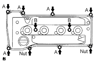
Install the cylinder head cover with the 8 bolts and 2 nuts.
- Torque:
- for bolt A
- 11 N*m { 112 kgf*cm, 8 ft.*lbf }
- for bolt B
- 14 N*m { 143 kgf*cm, 10 ft.*lbf }
- for nut
- 11 N*m { 112 kgf*cm, 8 ft.*lbf }
-
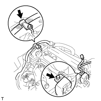
Install the 2 engine wires with the 2 bolts.
- Torque:
- 7.6 N*m { 77 kgf*cm, 67 in.*lbf }
-
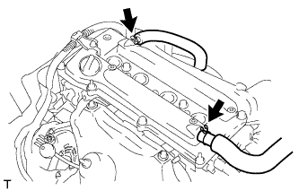
Connect the 2 ventilation hoses to the cylinder head cover.
-
-
INSTALL SPARK PLUG
-
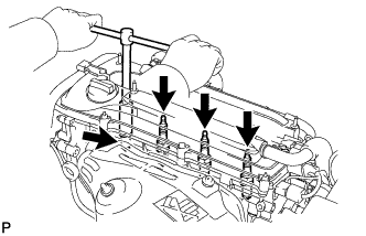
Using a 16 mm plug wrench, install the 4 spark plugs.
- Torque:
- 19 N*m { 194 kgf*cm, 14 ft.*lbf }
-
-
INSTALL IGNITION COIL ASSEMBLY
-
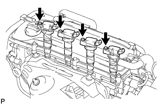
Install the 4 ignition coils with the 4 bolts.
- Torque:
- 9.0 N*m { 92 kgf*cm, 80 in.*lbf }
-
Connect the 4 ignition coil connectors.
-
-
INSPECT FOR OIL LEAK
-
Start the engine. Make sure that there are no oil leaks from the area that was worked on.
-
-
INSPECT IGNITION TIMING
Note
-
Turn all the electrical systems and the A/C off.
-
Inspect the ignition timing with the cooling fan off.
-
When checking the ignition timing, move the shift lever to N.
-
Warm up and stop the engine.
-
When using the intelligent tester:
-
Connect the intelligent tester to the DLC3.
-
Allow the engine to idle.
-
Enter the following menus: Powertrain / Engine and ECT / Data List / IGN Advance.
-
Read IGN Advance to check the ignition timing.
Standard ignition timing 5 to 15° BTDC @ idle -
Check that the ignition timing advances immediately when the engine speed is increased.
-
Turn the engine switch off.
-
Disconnect the intelligent tester from the DLC3.
-
-
When not using intelligent tester:
-
Remove the No. 1 engine cover Click here.
-
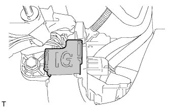
Open the ignition cover located to the right of the No. 4 ignition coil.
-
Pull out the wire harness from the IG cover.
-
Connect a timing light to the wire harness.
Note
Use a timing light that detects primary signals.
-
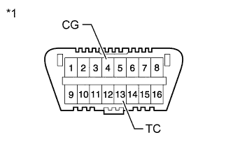
Text in Illustration *1 Front view of DLC3: Using SST, connect terminals 13 (TC) and 4 (CG) of the DLC3.
- SST
- 09843-18040
-
Allow the engine to idle and check the ignition timing.
Standard ignition timing 8 to 12° BTDC @ idle Tech Tips
Run the engine at 1000 to 1300 rpm for 5 seconds, and then check that the engine speed returns to the idling speed.
-
Remove SST from the DLC3.
-
Allow the engine to idle and check the ignition timing.
Standard ignition timing 5 to 15° BTDC -
Check that the ignition timing advances immediately when the engine speed is increased.
-
Turn the engine switch off.
-
Remove the timing light.
-
Close the IG cover.
-
Install the No. 1 engine cover Click here.
-
-
-
INSPECT ENGINE IDLE SPEED
Note
-
Turn all the electrical systems and the A/C off.
-
Inspect the ignition timing with the cooling fan off.
-
When checking the ignition timing, move the shift lever to N.
-
When using intelligent tester:
-
Turn off all the accessories and air conditioning.
-
Move the shift lever to P.
-
Connect the intelligent tester to the DLC3.
-
Warm up the engine.
-
Enter the following menus: Powertrain / Engine and ECT / Data List / Engine SPD.
-
Read Engine SPD to check the idle speed while the cooling fan is not rotating.
Standard idle speed 600 to 700 rpm -
Turn the engine switch off.
-
Disconnect the tester from the DLC3.
-
-
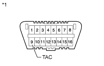
Text in Illustration *1 Front view of DLC3: When not using intelligent tester:
-
Turn off all the accessories and air conditioning.
-
Move the shift lever to P.
-
Connect SST to terminal 9 (TAC) of the DLC3, and then connect a tachometer to SST.
- SST
- 09843-18030
-
Warm up the engine.
-
Check the idle speed while the cooling fan is not rotating.
Standard idle speed 600 to 700 rpm -
Turn the engine switch off.
-
Remove the tachometer and disconnect SST from the DLC3.
-
-
-
INSPECT CO
Tech Tips
This check is used only to determine whether or not the idle CO complies with regulations.
-
Initial condition:
-
Engine at normal operating temperature
-
Air cleaner installed
-
All pipes and hoses of the air induction system connected
-
All accessories switched off
-
All vacuum lines properly connected
-
SFI system wiring connectors fully seated
-
Ignition timing set correctly
-
Shift lever in N
-
Tachometer and CO meter calibrated with engine idling
Note
If a CO meter is not available, do not attempt to adjust the idle mixture. Always use a CO meter when adjusting the idle mixture. It is unnecessary to use the idle mixture screw for adjustments if the vehicle is in good condition.
-
-
Warm up the engine by driving at a constant speed (approximately 50 km/h (31 mph)). Release the accelerator pedal after the engine coolant temperature becomes stable (85 to 90°C (185 to 194°F)) and idle the engine for 5 minutes.
-
Insert a tester probe at least 40 cm (1.31 ft) into the tailpipe.
-
Wait at least 1 minute before measurement to allow the concentration to stabilize. Complete the measurement within 3 minutes.
Idle CO concentration 1.0 to 2.0% -

If the CO concentration does not conform to regulations, adjust it by turning the idle mixture adjusting screw in the variable resistor with SST.
- SST
- 09243-00020
-
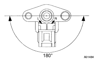
The idle mixture adjusting screw can be adjusted within a 180° range.
Tech Tips
-
If the CO concentration is within the specification, this adjustment is complete.
-
If the CO concentration cannot be corrected by idle mixture adjustment, see the table below for other possible causes.
-
-
Remove SST.
CO Problems Causes High Rough idle (black smoke from exhaust)
-
Clogged air filter
-
Plugged ventilation valve
-
Faulty SFI system:
-
Faulty fuel pressure regulator
-
Defective Engine Coolant Temperature (ECT) sensor
-
Faulty ECM
-
Faulty injectors
-
Faulty throttle body assembly
-
Faulty MAF meter
-
Variable resistor circuit Click here
-
-
-
INSTALL NO. 1 ENGINE COVER SUB-ASSEMBLY
-
Install the cover with the 2 nuts.
- Torque:
- 9.0 N*m { 92 kgf*cm, 80 in.*lbf }
-
-
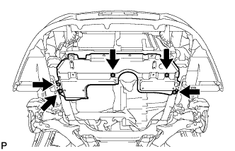
INSTALL REAR ENGINE UNDER COVER RH
-
Install the under cover with the 5 clips.
-
-
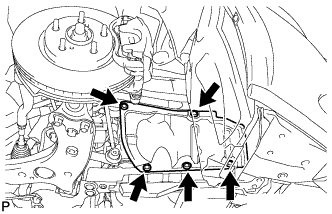
INSTALL NO. 1 ENGINE UNDER COVER (for Rough Road Area Specification Vehicles)
-
Install the under cover with the 3 bolts.
-
-
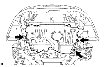
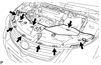
INSTALL NO. 1 ENGINE UNDER COVER
-
Install the under cover with the 5 clips.
-
-
INSTALL FRONT LOWER BUMPER ABSORBER
-
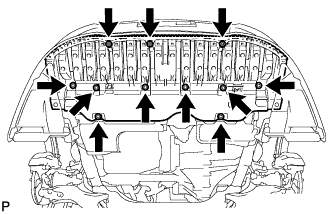
Install the front lower bumper absorber with the 8 bolts and 3 screws.
-
Install the 4 screws and 2 bolts.
-
-
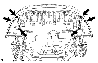
INSTALL RADIATOR SUPPORT OPENING COVER
-
Install the radiator support opening cover with the 9 clips.
-