VALVE CLEARANCE ADJUSTMENT

-
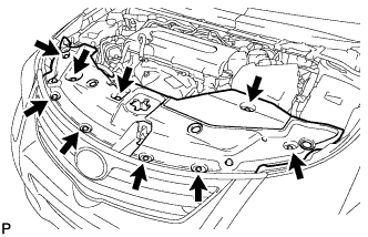
REMOVE RADIATOR SUPPORT OPENING COVER
-

Remove the 9 clips and radiator support opening cover.
-
-
REMOVE FRONT FENDER APRON SUB-ASSEMBLY RH
-
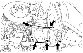
Remove the 5 clips and under cover.
-
-
REMOVE NO. 1 ENGINE COVER SUB-ASSEMBLY
-
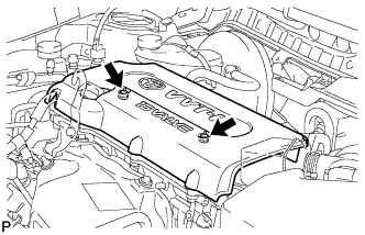
Remove the 2 nuts and engine cover.
-
-
REMOVE IGNITION COIL ASSEMBLY
-
Disconnect the 4 ignition coil connectors.
-
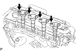
Remove the 4 bolts and 4 ignition coils.
-
-
REMOVE CYLINDER HEAD COVER SUB-ASSEMBLY
-
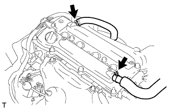
Disconnect the 2 ventilation hoses from the cylinder head cover.
-
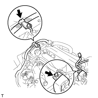
Remove the 2 bolts and disconnect the 2 engine wires.
-
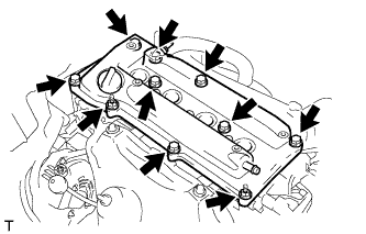
Remove the 8 bolts, 2 nuts and cylinder head cover.
-
-
SET NO. 1 CYLINDER TO TDC/COMPRESSION
-
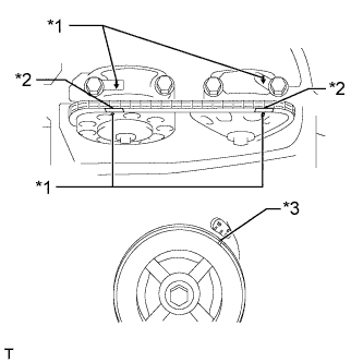
Text in Illustration *1 Timing Mark *2 Paint Mark *3 Groove Turn the crankshaft pulley until the groove and the timing mark "0" on the timing chain cover are aligned.
-
Check that each timing mark on the camshaft timing gear and sprocket is aligned with each timing mark located on the No. 1 and No. 2 bearing caps as shown in the illustration.
If not, turn the crankshaft pulley 1 revolution (360°) to align the timing marks as illustrated.
-
Place paint marks on the chain in alignment with the timing marks on the camshaft timing gear and camshaft timing sprocket.
-
-
CHECK VALVE CLEARANCE
-
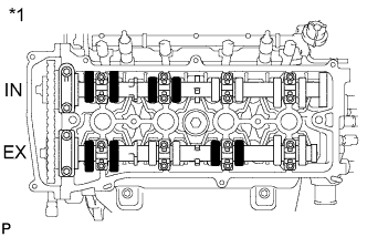
Text in Illustration *1 No. 1 Cylinder TDC/Compression Check only the valves indicated in the illustration.
-
Using a feeler gauge, measure the clearance between the valve lifter and camshaft.
Standard Valve Clearance (Cold) Item Specified Condition Intake 0.19 to 0.29 mm (0.00748 to 0.0114 in.) Exhaust 0.30 to 0.40 mm (0.0118 to 0.0157 in.) -
Record any out-of-specification valve clearance measurements. They will be used later to determine the required replacement valve clearance lifters.
-
-
Turn the crankshaft 1 revolution (360°) and set the No. 4 cylinder to TDC/compression.
-
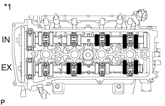
Text in Illustration *1 No. 4 Cylinder TDC/Compression Check only the valves indicated in the illustration.
-
Using a feeler gauge, measure the clearance between the valve lifter and camshaft.
Standard Valve Clearance (Cold) Item Specified Condition Intake 0.19 to 0.29 mm (0.00748 to 0.0114 in.) Exhaust 0.30 to 0.40 mm (0.0118 to 0.0157 in.) -
Record any out-of-specification valve clearance measurements. They will be used later to determine the required replacement valve lifters.
-
-
-
ADJUST VALVE CLEARANCE
-
Set the No. 1 cylinder to TDC/compression Click here.
-
Remove the camshaft and No. 2 camshaft Click here.
-
Remove the valve lifters.
-
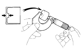
Using a micrometer, measure the thickness of the removed valve lifters.
-
Calculate the thickness of a new lifter so that the valve clearance comes within the specified values.
A Ideal new lifter thickness B Used lifter thickness C Measured valve clearance D Excess valve clearance New Lifter Thickness Item Specification Intake A = B + D Exhaust A = B + D for Intake D = C - 0.24 mm (0.00945 in.) for Exhaust D = C - 0.35 mm (0.0138 in.) Example (for Intake):
5.250 mm (0.2067 in.) (B) + 0.16 mm (0.00630 in.) (D) (0.40 mm (0.0158 in.) (C) - 0.24 mm (0.00945 in.)) = 5.410 mm (0.2130 in.) (A)
Tech Tips
Replace the 5.250 mm (0.2067 in.) lifter (B) with a new No. 42 lifter.
-
Select a new lifter with a thickness as close as possible to the calculated values.
Tech Tips
-
Lifters are available in 35 sizes in increments of 0.020 mm (0.000787 in.), from 5.060 to 5.740 mm (0.1992 to 0.2260 in.).
-
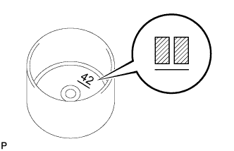
The identification number inside the valve lifters shows the first 2 decimal places of the thickness value (the illustration shows 5.420 mm (0.2134 in.)).
-
-
Valve lifter selection chart (Intake).
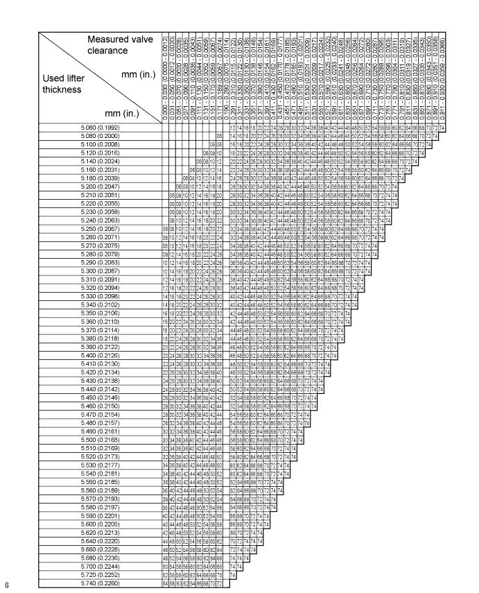
New Lifter Thickness Lifter No. Specified Condition Lifter No. Specified Condition Lifter No. Specified Condition 06 5.060 mm (0.1992 in.) 30 5.300 mm (0.2087 in.) 54 5.540 mm (0.2181 in.) 08 5.080 mm (0.2000 in.) 32 5.320 mm (0.2094 in.) 56 5.560 mm (0.2189 in.) 10 5.100 mm (0.2008 in.) 34 5.340 mm (0.2102 in.) 58 5.580 mm (0.2197 in.) 12 5.120 mm (0.2016 in.) 36 5.360 mm (0.2110 in.) 60 5.600 mm (0.2205 in.) 14 5.140 mm (0.2024 in.) 38 5.380 mm (0.2118 in.) 62 5.620 mm (0.2213 in.) 16 5.160 mm (0.2031 in.) 40 5.400 mm (0.2126 in.) 64 5.640 mm (0.2220 in.) 18 5.180 mm (0.2039 in.) 42 5.420 mm (0.2134 in.) 66 5.660 mm (0.2228 in.) 20 5.200 mm (0.2047 in.) 44 5.440 mm (0.2142 in.) 68 5.680 mm (0.2236 in.) 22 5.220 mm (0.2055 in.) 46 5.460 mm (0.2150) 70 5.700 mm (0.2244 in.) 24 5.240 mm (0.2063) 48 5.480 mm (0.2157) 72 5.720 mm (0.2252 in.) 26 5.260 mm (0.2071 in.) 50 5.500 mm (0.2165 in.) 74 5.740 mm (0.2260 in.) 28 5.280 mm (0.2079 in.) 52 5.520 mm (0.2173 in.) - - Standard intake valve clearance (cold) 0.19 to 0.29 mm (0.00748 to 0.0114 in.) Example:
The 5.250 mm (0.2067 in.) lifter is installed, and the measured clearance is 0.400 mm (0.0157 in.). Replace the 5.250 mm (0.2067 in.) lifter with a new No. 42 lifter.
-
Valve lifter selection chart (Exhaust).
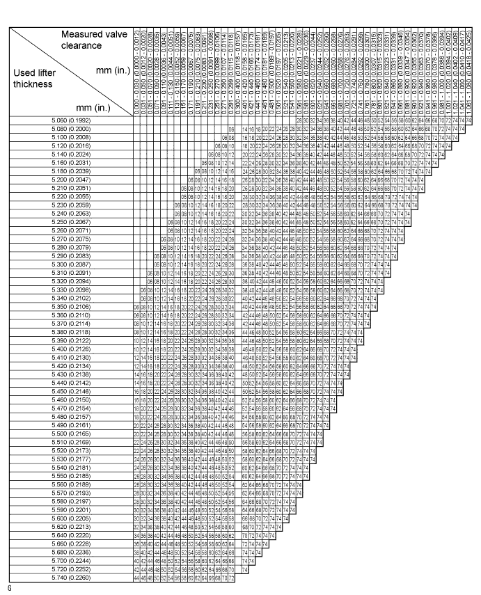
New Lifter Thickness Lifter No. Specified Condition Lifter No. Specified Condition Lifter No. Specified Condition 06 5.060 mm (0.1992 in.) 30 5.300 mm (0.2087 in.) 54 5.540 mm (0.2181 in.) 08 5.080 mm (0.2000 in.) 32 5.320 mm (0.2094 in.) 56 5.560 mm (0.2189 in.) 10 5.100 mm (0.2008 in.) 34 5.340 mm (0.2102 in.) 58 5.580 mm (0.2197 in.) 12 5.120 mm (0.2016 in.) 36 5.360 mm (0.2110 in.) 60 5.600 mm (0.2205 in.) 14 5.140 mm (0.2024 in.) 38 5.380 mm (0.2118 in.) 62 5.620 mm (0.2213 in.) 16 5.160 mm (0.2031 in.) 40 5.400 mm (0.2126 in.) 64 5.640 mm (0.2220 in.) 18 5.180 mm (0.2039 in.) 42 5.420 mm (0.2134 in.) 66 5.660 mm (0.2228 in.) 20 5.200 mm (0.2047 in.) 44 5.440 mm (0.2142 in.) 68 5.680 mm (0.2236 in.) 22 5.220 mm (0.2055 in.) 46 5.460 mm (0.2150 in.) 70 5.700 mm (0.2244 in.) 24 5.240 mm (0.2063 in.) 48 5.480 mm (0.2157 in.) 72 5.720 mm (0.2252 in.) 26 5.260 mm (0.2071 in.) 50 5.500 mm (0.2165 in.) 74 5.740 mm (0.2260 in.) 28 5.280 mm (0.2079 in.) 52 5.520 mm (0.2173 in.) - - Standard exhaust valve clearance (cold) 0.30 to 0.40 mm (0.0118 to 0.0157 in.) Example:
The 5.340 mm (0.2102 in.) lifter is installed, and the measured clearance is 0.430 mm (0.0169 in.). Replace the 5.340 mm (0.2102 in.) lifter with a new No. 42 lifter.
-
Install the selected valve lifter.
-
Install the camshaft and No. 2 camshaft Click here.
-
Set the No. 1 cylinder to TDC/compression Click here.
-
-
INSTALL CYLINDER HEAD COVER SUB-ASSEMBLY
-
Remove any old packing material from the contact surface.
-
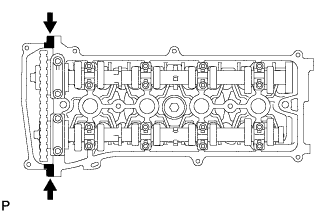
Apply seal packing to the 2 locations shown in the illustration.
Seal packing Toyota Genuine Seal Packing Black, Three Bond 1207B or Equivalent Note
-
Remove any oil from the contact surface.
-
Install the cylinder head cover within 3 minutes of applying seal packing.
-
Do not add engine oil for at least 2 hours after installing the cylinder head cover.
-
-
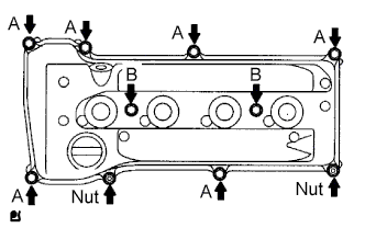
Install the cylinder head cover with the 8 bolts and 2 nuts.
- Torque:
- for bolt A
- 11 N*m { 112 kgf*cm, 8 ft.*lbf }
- for bolt B
- 14 N*m { 143 kgf*cm, 10 ft.*lbf }
- for nut
- 11 N*m { 112 kgf*cm, 8 ft.*lbf }
-
Install the 2 engine wires with the 2 bolts.
- Torque:
- 7.6 N*m { 77 kgf*cm, 67 in.*lbf }
-
Connect the 2 ventilation hoses to the cylinder head cover.
-
-
INSTALL IGNITION COIL ASSEMBLY
-
Install the 4 ignition coils with the 4 bolts.
- Torque:
- 9.0 N*m { 92 kgf*cm, 80 in.*lbf }
-
Connect the 4 ignition coil connectors.
-
-
INSPECT FOR OIL LEAK
-
Start the engine. Make sure that there are no oil leaks from the area that was worked on.
-
-
INSPECT IGNITION TIMING
Note
-
Turn all the electrical systems and the A/C off.
-
Inspect the ignition timing with the cooling fan off.
-
When checking the ignition timing, move the shift lever to N.
-
Warm up and stop the engine.
-
When using the intelligent tester:
-
Connect the intelligent tester to the DLC3.
-
Allow the engine to idle.
-
Enter the following menus: Powertrain / Engine and ECT / Data List / IGN Advance.
-
Read IGN Advance to check the ignition timing.
Standard ignition timing 5 to 15° BTDC @ idle -
Check that the ignition timing advances immediately when the engine speed is increased.
-
Turn the engine switch off.
-
Disconnect the intelligent tester from the DLC3.
-
-
When not using intelligent tester:
-
Remove the No. 1 engine cover Click here.
-
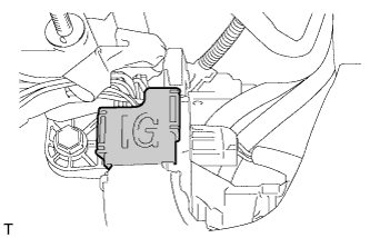
Open the ignition cover located to the right of the No. 4 ignition coil.
-
Pull out the wire harness from the IG cover.
-
Connect a timing light to the wire harness.
Note
Use a timing light that detects primary signals.
-
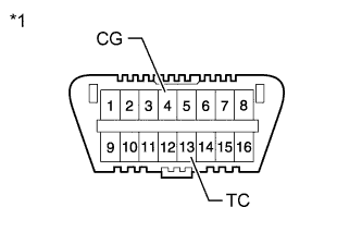
Text in Illustration *1 Front view of DLC3: Using SST, connect terminals 13 (TC) and 4 (CG) of the DLC3.
- SST
- 09843-18040
-
Allow the engine to idle and check the ignition timing.
Standard ignition timing 8 to 12° BTDC @ idle Tech Tips
Run the engine at 1000 to 1300 rpm for 5 seconds, and then check that the engine speed returns to the idling speed.
-
Remove SST from the DLC3.
-
Allow the engine to idle and check the ignition timing.
Standard ignition timing 5 to 15° BTDC -
Check that the ignition timing advances immediately when the engine speed is increased.
-
Turn the engine switch off.
-
Remove the timing light.
-
Close the IG cover.
-
Install the No. 1 engine cover Click here.
-
-
-
INSTALL NO. 1 ENGINE COVER SUB-ASSEMBLY
-

Install the cover with the 2 nuts.
- Torque:
- 9.0 N*m { 92 kgf*cm, 80 in.*lbf }
-
-
INSTALL FRONT FENDER APRON SUB-ASSEMBLY RH
-
Install the under cover with the 5 clips.
-
-
INSTALL RADIATOR SUPPORT OPENING COVER
-
Install the radiator support opening cover with the 9 clips.
-