SFI SYSTEM, Diagnostic DTC:P0500

| DTC Code | DTC Name |
|---|---|
| P0500 | Vehicle Speed Sensor "A" |
DESCRIPTION
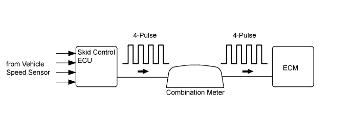
The vehicle speed sensor monitors the wheel rotation speed and sends a signal to the skid control ECU. The skid control ECU converts the wheel speed signal into a 4-pulse signal and transmits it to the ECM via the combination meter. The ECM determines the vehicle speed based on the frequency of the pulse signals.
Tech Tips
Each ECU controls its respective system based on this pulse signal, and if a short occurs in any of the ECUs or in the wire harness connected to an ECU, all systems that use the vehicle speed signal to perform control will not operate normally.
| DTC No. | DTC Detection Condition | Trouble Area |
|---|---|---|
| P0500 | While the vehicle is being driven, no vehicle speed sensor signal is sent to the ECM (2 trip detection logic). |
|
-
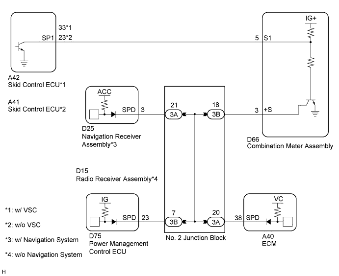
*1: w/ Entry and Start System
-
*2: w/o Navigation System
-
*3: w/ Navigation System
WIRING DIAGRAM
INSPECTION PROCEDURE
Tech Tips
Read freeze frame data using the intelligent tester. Freeze frame data records the engine condition when malfunctions are detected. When troubleshooting, freeze frame data can help determine if the vehicle was moving or stationary, if the engine was warmed up or not, if the air fuel ratio was lean or rich, and other data from the time the malfunction occurred.
PROCEDURE
-
READ VALUE USING INTELLIGENT TESTER (VEHICLE SPEED)
-
Connect the intelligent tester to the DLC3.
-
Turn the ignition switch to ON.
-
Turn the tester on.
-
Enter the following menus: Powertrain / Engine and ECT / Data List / Vehicle Speed.
-
Drive the vehicle.
-
Read the value displayed on the tester.
OK Vehicle speeds displayed on tester and speedometer display are equal.
NG 
CHECK COMBINATION METER SYSTEM Click here
OK 
CHECK FOR INTERMITTENT PROBLEMS Click here
-
-
CHECK COMBINATION METER SYSTEM
-
The circuits that send vehicle speed signals to this system are inspected in the meter system Click here.
-
During the inspection in the meter section, if there is an instruction to proceed to the next suspected area, proceed to the next step.
NEXT 
-
-
CHECK HARNESS AND CONNECTOR (COMBINATION METER ASSEMBLY - ECM)
-
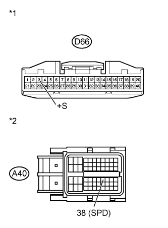
Text in Illustration *1 Front view of wire harness connector
(to Combination Meter Assembly)
*2 Front view of wire harness connector
(to ECM)
Disconnect the combination meter assembly connector.
-
Disconnect the ECM connector.
-
Measure the resistance according to the value(s) in the table below.
Standard Resistance Tester Connection Condition Specified Condition D66-3 (+S) - A40-38 (SPD) Always Below 1 Ω -
Reconnect the combination meter assembly connector.
-
Reconnect the ECM connector.
NG
CHECK HARNESS AND CONNECTOR (ECM - NO. 2 JUNCTION BLOCK) Click here
OK
REPLACE ECM Click here
-
-
CHECK HARNESS AND CONNECTOR (ECM - NO. 2 JUNCTION BLOCK)
-
Disconnect the ECM connector.
-
Disconnect the No. 2 junction block connector.
-
Measure the resistance according to the value(s) in the table below.
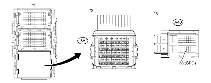
Standard Resistance Tester Connection Condition Specified Condition 3A-20 - A40-38 (SPD) Always Below 1 Ω Text in Illustration *1 No. 2 Junction Block *2 Front view of wire harness connector
(to No. 2 Junction Block)
*3 Front view of wire harness connector
(to ECM)
-
Reconnect the ECM connector.
-
Reconnect the No. 2 junction block connector.
NG 
REPAIR OR REPLACE HARNESS OR CONNECTOR (ECM - NO. 2 JUNCTION BLOCK)
OK
REPAIR OR REPLACE HARNESS OR CONNECTOR (NO. 2 JUNCTION BLOCK)
-