SFI SYSTEM, Diagnostic DTC:P0617

| DTC Code | DTC Name |
|---|---|
| P0617 | Starter Relay Circuit High |
DESCRIPTION
While the engine is being cranked, battery voltage is applied to terminal STA of the ECM.
If the ECM detects the starter signal (STA signal) while the vehicle is being driven, it determines that there is a malfunction in the STA circuit. The ECM then illuminates the MIL and stores the DTC.
| DTC No. | DTC Detection Condition | Trouble Area |
|---|---|---|
| P0617 | When conditions (a), (b) and (c) are met, a positive (+B) battery voltage of 10.5 V or higher is applied to the ECM for 20 seconds (1 trip detection logic):
|
|
-
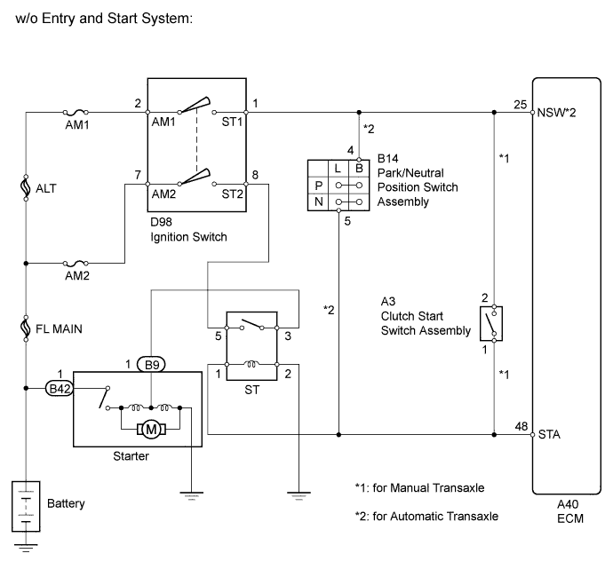
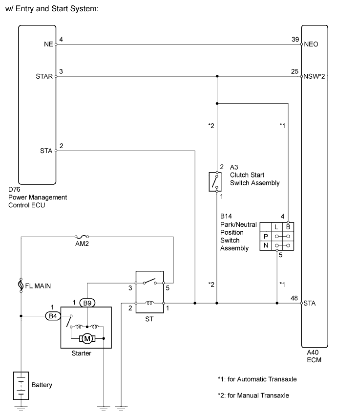
*1: w/ Entry and Start System
-
*2: w/o Entry and Start System
-
*3: for Manual Transaxle
-
*4: for Automatic Transaxle
WIRING DIAGRAM
INSPECTION PROCEDURE
Note
Inspect the fuses for circuits related to this system before performing the following inspection procedure.
Tech Tips
-
The following troubleshooting flowchart is based on the premise that the engine can be cranked normally.
If the engine does not crank, proceed to the Problem Symptoms Table Click here.
-
Read freeze frame data using the intelligent tester. The ECM records vehicle and driving condition information as freeze frame data the moment a DTC is stored. When troubleshooting, freeze frame data can help determine if the vehicle was moving or stationary, if the engine was warmed up or not, and other data from the time the malfunction occurred.
PROCEDURE
-
CHECK IF VEHICLE IS EQUIPPED WITH ENTRY AND START SYSTEM
-
Check if the vehicle is equipped with an entry and start system.
Result Result Proceed to w/o Entry and Start System A w/ Entry and Start System B
B 
READ VALUE USING INTELLIGENT TESTER (STARTER SIGNAL) Click here
A 
-
-
READ VALUE USING INTELLIGENT TESTER (STARTER SIGNAL)
-
Connect the intelligent tester to the DLC3.
-
Turn the ignition switch to ON and turn the tester on.
-
Enter the following menus: Powertrain / Engine and ECT / Data List / Starter Signal.
-
Read the value displayed on the tester when the ignition switch is turned to ON and when the engine is started.
OK Condition Starter Signal Ignition switch ON OFF Engine started ON Result Result Proceed to OK A NG (for Manual transaxle) B NG (for Automatic transaxle) C
B
INSPECT IGNITION SWITCH ASSEMBLY Click here
C
INSPECT IGNITION SWITCH ASSEMBLY Click here
A 
CHECK FOR INTERMITTENT PROBLEMS Click here
-
-
INSPECT IGNITION SWITCH ASSEMBLY
-
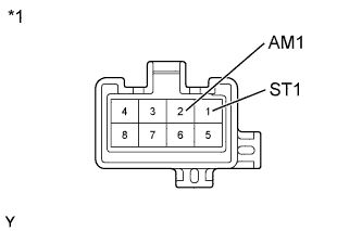
Text in Illustration *1 Component without harness connected
(Ignition Switch Assembly)
Disconnect the ignition switch assembly connector.
-
Measure the resistance according to the value(s) in the table below.
Standard Resistance Tester Connection Switch Condition Specified Condition Any terminals LOCK 10 kΩ or higher 2 (AM1) - 1 (ST1) START Below 1 Ω -
Reconnect the ignition switch assembly connector.
NG 
REPLACE IGNITION SWITCH ASSEMBLY Click here
OK
-
-
CHECK HARNESS AND CONNECTOR (IGNITION SWITCH ASSEMBLY - CLUTCH START SWITCH ASSEMBLY)
-
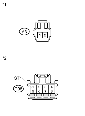
Text in Illustration *1 Front view of wire harness connector
(to Clutch Start Switch Assembly)
*2 Front view of wire harness connector
(to Ignition Switch Assembly)
Disconnect the clutch start switch assembly connector.
-
Disconnect the ignition switch assembly connector.
-
Measure the resistance according to the value(s) in the table below.
Standard Resistance Tester Connection Condition Specified Condition D98-1 (ST1) or A3-2 - Body ground Always 10 kΩ or higher -
Reconnect the clutch start switch assembly connector.
-
Reconnect the ignition switch assembly connector.
NG
REPAIR OR REPLACE HARNESS OR CONNECTOR (IGNITION SWITCH ASSEMBLY - CLUTCH START SWITCH ASSEMBLY)
OK
-
-
CHECK HARNESS AND CONNECTOR (CLUTCH START SWITCH ASSEMBLY - STARTER RELAY [ST])
-
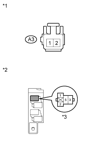
Text in Illustration *1 Front view of wire harness connector
(to Clutch Start Switch Assembly)
*2 No. 1 Relay Block *3 Starter Relay (ST) Disconnect the clutch start switch assembly connector.
-
Remove the starter relay (ST) from the No. 1 relay block.
-
Measure the resistance according to the value(s) in the table below.
Standard Resistance Tester Connection Condition Specified Condition Starter relay (ST) terminal 1 or A3-1 - Body ground Always 10 kΩ or higher -
Reconnect the clutch start switch assembly connector.
-
Reinstall the starter relay (ST).
NG
REPAIR OR REPLACE HARNESS OR CONNECTOR (CLUTCH START SWITCH ASSEMBLY - STARTER RELAY [ST])
OK
-
-
CHECK HARNESS AND CONNECTOR (CLUTCH START SWITCH ASSEMBLY - ECM)
-
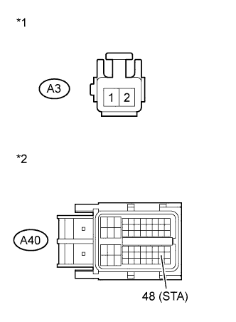
Text in Illustration *1 Front view of wire harness connector
(to Clutch Start Switch Assembly)
*2 Front view of wire harness connector
(to ECM)
Disconnect the ECM connector.
-
Disconnect the clutch start switch assembly connector.
-
Remove the starter relay (ST) from the No. 1 relay block.
-
Measure the resistance according to the value(s) in the table below.
Standard Resistance Tester Connection Condition Specified Condition A3-1 or A40-48 (STA) - Body ground Always 10 kΩ or higher -
Reconnect the ECM connector.
-
Reconnect the clutch start switch assembly connector.
-
Reinstall the starter relay (ST).
NG
REPAIR OR REPLACE HARNESS OR CONNECTOR (CLUTCH START SWITCH ASSEMBLY - ECM)
OK
REPLACE ECM Click here
-
-
INSPECT IGNITION SWITCH ASSEMBLY
-
Text in Illustration *1 Component without harness connected
(Ignition Switch Assembly)
Disconnect the ignition switch assembly connector.
-
Measure the resistance according to the value(s) in the table below.
Standard Resistance Tester Connection Switch Condition Specified Condition Any terminals LOCK 10 kΩ or higher 2 (AM1) - 1 (ST1) START Below 1 Ω -
Reconnect the ignition switch assembly connector.
NG
REPLACE IGNITION SWITCH ASSEMBLY Click here
OK
-
-
CHECK HARNESS AND CONNECTOR (IGNITION SWITCH ASSEMBLY - PARK/NEUTRAL POSITION SWITCH)
-
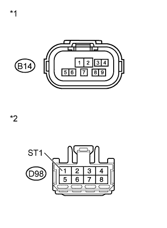
Text in Illustration *1 Front view of wire harness connector
(to Park/Neutral Position Switch)
*2 Front view of wire harness connector
(to Ignition Switch Assembly)
Disconnect the park/neutral position switch connector.
-
Disconnect the ignition switch assembly connector.
-
Measure the resistance according to the value(s) in the table below.
Standard Resistance Tester Connection Condition Specified Condition D98-1 (ST1) or B14-4 - Body ground Always 10 kΩ or higher -
Reconnect the park/neutral position switch connector.
-
Reconnect the ignition switch assembly connector.
NG
REPAIR OR REPLACE HARNESS OR CONNECTOR (IGNITION SWITCH ASSEMBLY - PARK/NEUTRAL POSITION SWITCH)
OK
-
-
CHECK HARNESS AND CONNECTOR (PARK/NEUTRAL POSITION SWITCH - STARTER RELAY [ST])
-
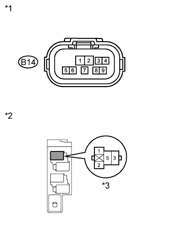
Text in Illustration *1 Front view of wire harness connector
(to Park/Neutral Position Switch)
*2 No. 1 Relay Block *3 Starter Relay (ST) Disconnect the park/neutral position switch connector.
-
Remove the starter relay (ST) from the No. 1 relay block.
-
Measure the resistance according to the value(s) in the table below.
Standard Resistance Tester Connection Condition Specified Condition Starter relay (ST) terminal 1 or B14-5 - Body ground Always 10 kΩ or higher -
Reconnect the park/neutral position switch connector.
-
Reinstall the starter relay (ST).
NG
REPAIR OR REPLACE HARNESS OR CONNECTOR (PARK/NEUTRAL POSITION SWITCH - STARTER RELAY [ST])
OK
-
-
CHECK HARNESS AND CONNECTOR (PARK/NEUTRAL POSITION SWITCH - ECM)
-
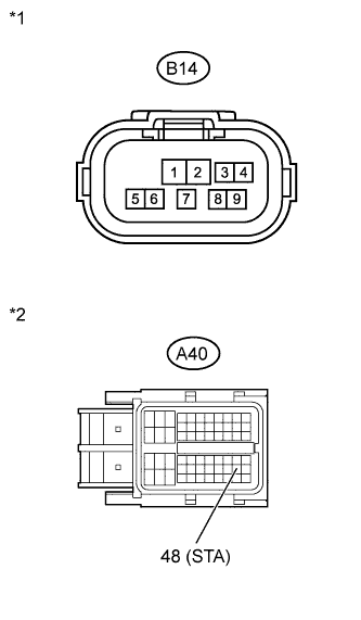
Text in Illustration *1 Front view of wire harness connector
(to Park/Neutral Position Switch)
*2 Front view of wire harness connector
(to ECM)
Disconnect the park/neutral position switch connector.
-
Disconnect the ECM connector.
-
Remove the starter relay (ST) from the No. 1 relay block.
-
Measure the resistance according to the value(s) in the table below.
Standard Resistance Tester Connection Condition Specified Condition B14-5 or A40-48 (STA) - Body ground Always 10 kΩ or higher -
Reconnect the park/neutral position switch connector.
-
Reconnect the ECM connector.
-
Reinstall the starter relay (ST).
NG
REPAIR OR REPLACE HARNESS OR CONNECTOR (PARK/NEUTRAL POSITION SWITCH - ECM)
OK
REPLACE ECM Click here
-
-
READ VALUE USING INTELLIGENT TESTER (STARTER SIGNAL)
-
Connect the intelligent tester to the DLC3.
-
Turn the ignition switch to ON and turn the tester on.
-
Enter the following menus: Powertrain / Engine and ECT / Data List / Starter Signal.
-
Read the value displayed on the tester when the ignition switch is ON and when the engine is started.
OK Condition Starter Signal Ignition switch ON OFF Engine started ON Result Result Proceed to OK A NG (for Manual transaxle) B NG (for Automatic transaxle) C
B
CHECK HARNESS AND CONNECTOR (CLUTCH START SWITCH ASSEMBLY - POWER MANAGEMENT CONTROL ECU) Click here
C
CHECK HARNESS AND CONNECTOR (PARK/NEUTRAL POSITION SWITCH - POWER MANAGEMENT CONTROL ECU) Click here
A
CHECK FOR INTERMITTENT PROBLEMS Click here
-
-
CHECK HARNESS AND CONNECTOR (CLUTCH START SWITCH ASSEMBLY - POWER MANAGEMENT CONTROL ECU)
-
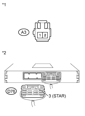
Text in Illustration *1 Front view of wire harness connector
(to Clutch Start Switch Assembly)
*2 Rear view of wire harness connector
(to Power Management Control ECU)
Disconnect the clutch start switch assembly connector.
-
Disconnect the power management control ECU connector.
-
Measure the resistance according to the value(s) in the table below.
Standard Resistance Tester Connection Condition Specified Condition A3-2 or D76-3 (STAR) - Body ground Always 10 kΩ or higher -
Reconnect the clutch start switch assembly connector.
-
Reconnect the power management control ECU connector.
NG
REPAIR OR REPLACE HARNESS OR CONNECTOR (CLUTCH START SWITCH ASSEMBLY - POWER MANAGEMENT CONTROL ECU)
OK
-
-
CHECK HARNESS AND CONNECTOR (CLUTCH START SWITCH ASSEMBLY - STARTER RELAY [ST])
-
Text in Illustration *1 Front view of wire harness connector
(to Clutch Start Switch Assembly)
*2 No. 1 Relay Block *3 Starter Relay (ST) Disconnect the clutch start switch assembly connector.
-
Remove the starter relay (ST) from the No. 1 relay block.
-
Measure the resistance according to the value(s) in the table below.
Standard Resistance Tester Connection Condition Specified Condition Starter relay (ST) terminal 1 or A3-1 - Body ground Always 10 kΩ or higher -
Reconnect the clutch start switch assembly connector.
-
Reinstall the starter relay (ST).
NG
REPAIR OR REPLACE HARNESS OR CONNECTOR (CLUTCH START SWITCH ASSEMBLY - STARTER RELAY [ST])
OK
-
-
CHECK HARNESS AND CONNECTOR (CLUTCH START SWITCH ASSEMBLY - ECM)
-
Text in Illustration *1 Front view of wire harness connector
(to Clutch Start Switch Assembly)
*2 Front view of wire harness connector
(to ECM)
Disconnect the ECM connector.
-
Disconnect the clutch start switch assembly connector.
-
Remove the starter relay (ST) from the No. 1 relay block.
-
Measure the resistance according to the value(s) in the table below.
Standard Resistance Tester Connection Condition Specified Condition A3-1 or A40-48 (STA) - Body ground Always 10 kΩ or higher -
Reconnect the ECM connector.
-
Reconnect the clutch start switch assembly connector.
-
Reinstall the starter relay (ST).
NG
REPAIR OR REPLACE HARNESS OR CONNECTOR (CLUTCH START SWITCH ASSEMBLY - ECM)
OK
REPLACE ECM Click here
-
-
CHECK HARNESS AND CONNECTOR (PARK/NEUTRAL POSITION SWITCH - POWER MANAGEMENT CONTROL ECU)
-
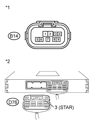
Text in Illustration *1 Front view of wire harness connector
(to Park/Neutral Position Switch)
*2 Rear view of wire harness connector
(to Power Management Control ECU)
Disconnect the park/neutral position switch connector.
-
Disconnect the power management control ECU connector.
-
Measure the resistance according to the value(s) in the table below.
Standard Resistance Tester Connection Condition Specified Condition B14-4 or D76-3 (STAR) - Body ground Always 10 kΩ or higher -
Reconnect the park/neutral position switch connector.
-
Reconnect the power management control ECU connector.
NG
REPAIR OR REPLACE HARNESS OR CONNECTOR (PARK/NEUTRAL POSITION SWITCH - POWER MANAGEMENT CONTROL ECU)
OK
-
-
CHECK HARNESS AND CONNECTOR (PARK/NEUTRAL POSITION SWITCH - STARTER RELAY [ST])
-
Text in Illustration *1 Front view of wire harness connector
(to Park/Neutral Position Switch)
*2 No. 1 Relay Block *3 Starter Relay (ST) Disconnect the park/neutral position switch connector.
-
Remove the starter relay (ST) from the No. 1 relay block.
-
Measure the resistance according to the value(s) in the table below.
Standard Resistance Tester Connection Condition Specified Condition Starter relay (ST) terminal 1 or B14-5 - Body ground Always 10 kΩ or higher -
Reconnect the park/neutral position switch connector.
-
Reinstall the starter relay (ST).
NG
REPAIR OR REPLACE HARNESS OR CONNECTOR (PARK/NEUTRAL POSITION SWITCH - STARTER RELAY [ST])
OK
-
-
CHECK HARNESS AND CONNECTOR (PARK/NEUTRAL POSITION SWITCH - ECM)
-
Text in Illustration *1 Front view of wire harness connector
(to Park/Neutral Position Switch)
*2 Front view of wire harness connector
(to ECM)
Disconnect the park/neutral position switch connector.
-
Disconnect the ECM connector.
-
Remove the starter relay (ST) from the No. 1 relay block.
-
Measure the resistance according to the value(s) in the table below.
Standard Resistance Tester Connection Condition Specified Condition B14-5 or A40-48 (STA) - Body ground Always 10 kΩ or higher -
Reconnect the park/neutral position switch connector.
-
Reconnect the ECM connector.
-
Reinstall the starter relay (ST).
NG
REPAIR OR REPLACE HARNESS OR CONNECTOR (PARK/NEUTRAL POSITION SWITCH - ECM)
OK
REPLACE ECM Click here
-