ECM REMOVAL

-
REMOVE ENGINE ROOM SIDE COVER
-
Remove the clip and engine room side cover.
-
-
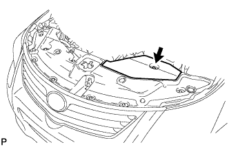
REMOVE RADIATOR SUPPORT OPENING COVER
-
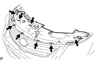
Remove the 8 clips and radiator support opening cover.
-
-
DISCONNECT CABLE FROM NEGATIVE BATTERY TERMINAL
Note
-
w/ Navigation System (for HDD):
After the ignition switch is turned off, the HDD navigation system requires approximately a minute to record various types of memory and settings. As a result, after turning the ignition switch off, wait a minute or more before disconnecting the cable from the negative (-) battery terminal.
-
When disconnecting the cable, some systems need to be initialized after the cable is reconnected Click here.
-
-
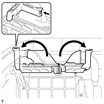
REMOVE NO. 2 CYLINDER HEAD COVER
-
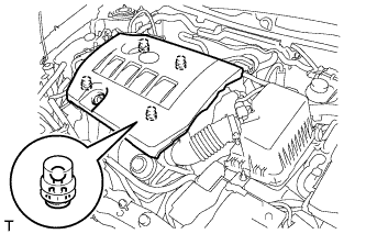
Hold the rear of the cover and raise it to detach the 2 clips on the rear of the cover. Continue to raise the cover to detach the 2 clips on the front of the cover and remove the cover.
Note
Attempting to detach both front and rear clips at the same time may cause the cover to break.
-
-
REMOVE AIR CLEANER CAP SUB-ASSEMBLY
-
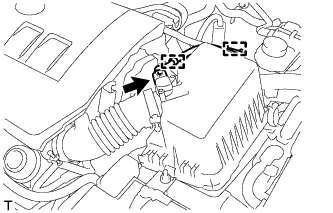
Disconnect the mass air flow meter connector.
-
Detach the wire harness from the 2 clamps.
-
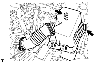
Disconnect the 2 clamps.
-
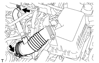
Disconnect the ventilation hose.
-
Loosen the band and remove the air cleaner cap.
-
-
REMOVE AIR CLEANER CASE SUB-ASSEMBLY
-
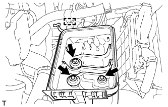
Detach the wire harness clamp from the air cleaner case.
-
Remove the 3 bolts and air cleaner case.
-
-
REMOVE NO. 1 AIR CLEANER INLET
-
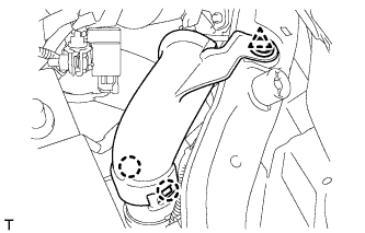
Remove the clip.
-
Detach the 2 claws and remove the No. 1 air cleaner inlet.
-
-
DISCONNECT NO. 2 AIR CLEANER INLET
-
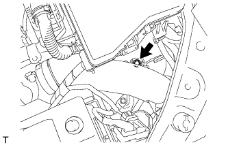
Remove the bolt and disconnect the No. 2 air cleaner inlet from the vehicle body.
-
-
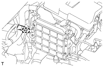
REMOVE ECM
-
for Manual Transaxle:
Disconnect the wire harness clamp.
-
Disconnect the 2 ECM connectors.
-
Raise the 2 levers while pushing the locks on the levers and disconnect the 2 ECM connectors.
Note
After disconnecting the connectors, make sure that dirt, water or other foreign matter does not contact the connecting parts of the connectors.
-
-
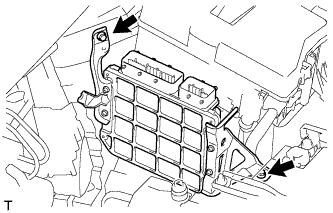
Remove the 2 bolts and ECM.
-
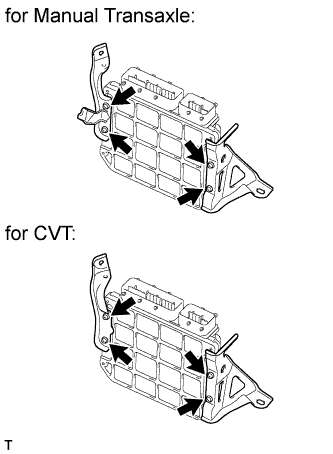
Remove the 4 screws, No. 1 ECM bracket and No. 2 ECM bracket.
-