БАРАБАН МУФТЫ И ПЕРВИЧНЫЙ ВАЛ В СБОРЕ РАЗБОРКА

-
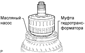
FIX CLUTCH DRUM AND INPUT SHAFT ASSEMBLY
-
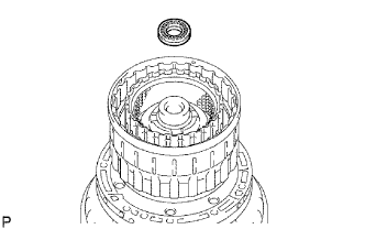
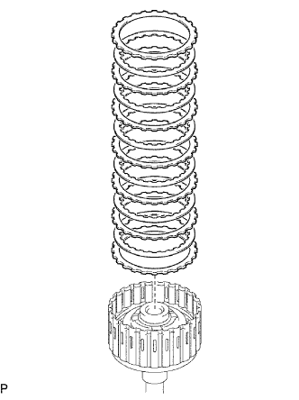
Place the oil pump onto the torque converter clutch, and then place the clutch drum and input shaft assembly onto the oil pump.
-
-
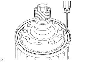
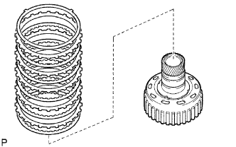
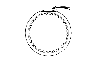
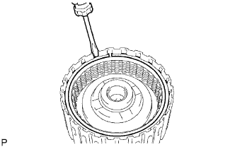
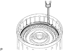
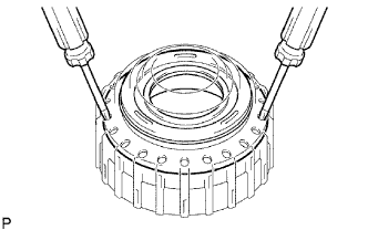
REMOVE REVERSE CLUTCH HUB SUB-ASSEMBLY
-
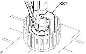
Using a screwdriver, remove the snap ring from the clutch drum and input shaft assembly.
-
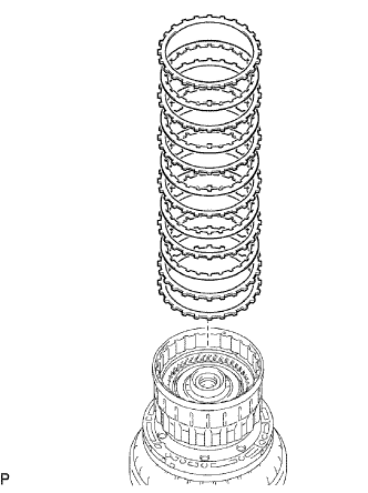
Remove the reverse clutch hub sub-assembly, reverse clutch reaction sleeve, clutch cushion, plate reverse clutch flange, 5 reverse clutch discs and 4 clutch plates from the clutch drum assembly.
-
-
REMOVE REVERSE CLUTCH REACTION SLEEVE
-
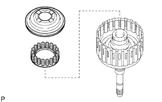
Remove the reverse clutch reaction sleeve from the reverse clutch hub sub-assembly.
-
-
REMOVE REAR CLUTCH DISC
-
Remove the clutch cushion plate, reverse clutch flange, 4 plates and 5 discs from the reverse clutch hub.
-
-
INSPECT REAR CLUTCH DISC
-
Replace all discs if one of the following problems is present: 1) a disc, plate or flange is worn or burnt, 2) the lining of a disc is peeled off or discolored, or 3) grooves or printed numbers have even a little bit of damage.
Note
Before assembling new discs, soak them in ATF for at least 15 minutes.
-
-
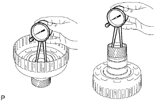
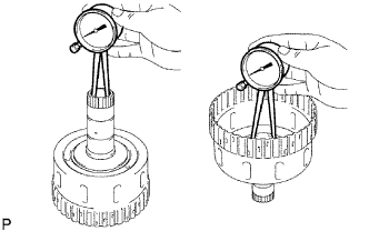
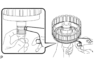
INSPECT REVERSE CLUTCH HUB SUB-ASSEMBLY
-
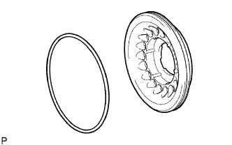
Using a dial indicator, measure the inside diameter of the reverse clutch hub bushing.
Standard inside diameter 35.812 to 35.837 mm (1.4099 to 1.4109 in.) Maximum inside diameter 35.887 mm (1.4129 in.)
-
If the inside diameter is greater than the maximum, replace the reverse clutch hub.
-
-
-
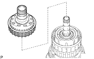
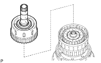
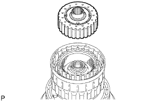
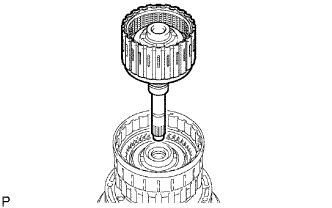
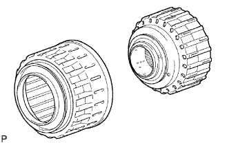
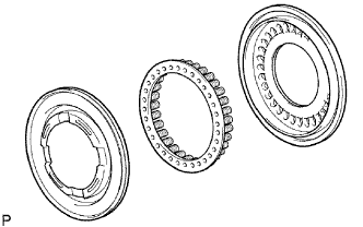
REMOVE FORWARD CLUTCH HUB SUB-ASSEMBLY
-
Remove the forward clutch hub sub-assembly from the clutch drum assembly.
-
Remove the 2 thrust needle roller bearings from the forward clutch hub sub-assembly.
-
-
INSPECT FORWARD CLUTCH HUB SUB-ASSEMBLY
-
Using a dial indicator, measure the inside diameter of the forward clutch hub bushing.
Standard inside diameter 26.037 to 26. 062 mm (1.0251 to 1.0261 in.) Maximum inside diameter 26.112 mm (1.028 in.)
-
If the inside diameter is greater than the maximum, replace the forward clutch hub.
-
-
-
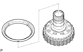
REMOVE MULTIPLE DISC CLUTCH HUB
-
Remove the multiple disc clutch hub from the clutch drum assembly.
-
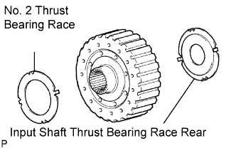
Remove the No. 2 thrust bearing race and input shaft thrust bearing race rear from the multiple disc clutch hub.
-
-
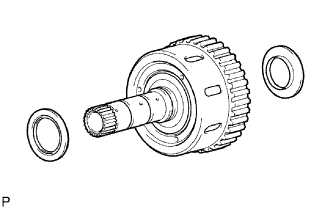
REMOVE INPUT SHAFT ASSEMBLY
-
Remove the thrust needle roller bearing from the clutch drum assembly.
-
Remove the input shaft assembly from the clutch drum assembly.
-
-
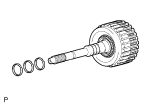
REMOVE INPUT SHAFT OIL SEAL RING
-
Remove the 3 oil seal rings from the input shaft assembly.
-
-
REMOVE FORWARD MULTIPLE DISC CLUTCH DISC
-
Using a screwdriver, remove the hole snap ring.
-
Remove the 2 flanges, 6 discs and 5 plates from the input shaft assembly.
-
-
INSPECT FORWARD MULTIPLE DISC CLUTCH DISC
-
Replace all discs if one of the following problems is present: 1) a disc, plate or flange is worn or burnt, 2) the lining of a disc is peeled off or discolored, or 3) grooves or printed numbers have even a little bit of damage.
Note
Before assembling new discs, soak them in ATF for at least 15 minutes.
-
-
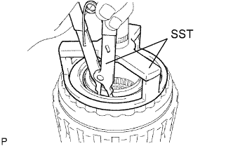
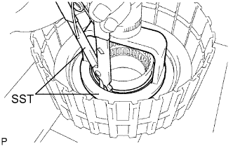
REMOVE NO. 1 CLUTCH BALANCER
-
Place SST on the No. 1 clutch balancer, and compress the return spring with a press.
- SST
- 09350-30020 ( 09350-07040, 09350-07070 )
-
Remove the No. 1 clutch balancer and forward clutch return spring from the input shaft assembly.
-
Remove the O-ring from the No. 1 clutch balancer.
-
-
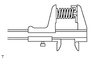
INSPECT FORWARD CLUTCH RETURN SPRING SUB-ASSEMBLY
-
Using a vernier caliper, measure the free length of the spring together with the spring seat.
Standard free length 26.74 mm (1.053 in.)
-
-
REMOVE FORWARD CLUTCH PISTON
-
Holding the forward clutch piston by hand, apply compressed air (392 kPa, 4.0 kgf/cm2, 57 psi) to the input shaft to remove the forward clutch piston.
-
Remove the 2 O-rings from the forward clutch piston.
-
-
REMOVE REVERSE CLUTCH FLANGE
-
Remove the reverse clutch flange from the clutch drum assembly.
-
-
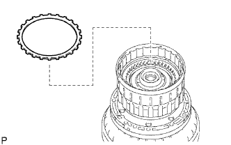
REMOVE DIRECT CLUTCH DISC
-
Using a screwdriver, remove the 2 hole snap rings from the clutch drum assembly.
-
Remove the reverse clutch flange, 6 plates and 5 discs from the clutch drum assembly.
-
-
INSPECT DIRECT CLUTCH DISC
-
REMOVE NO. 3 CLUTCH BALANCER
-
Place SST on the No. 3 clutch balancer, and compress the return spring with a press.
- SST
- 09387-00070
- 09350-30020 ( 09350-07070 )
-
Remove the snap ring and clutch balancer.
-
-
REMOVE REVERSE CLUTCH RETURN SPRING SUB-ASSEMBLY
-
Remove the reverse clutch return spring and O-ring from the reverse clutch piston.
-
-
INSPECT REVERSE CLUTCH RETURN SPRING SUB-ASSEMBLY
-
Using a vernier caliper, measure the free length of the spring together with the spring seat.
Standard free length 21.04 mm (0.828 in.)
-
-
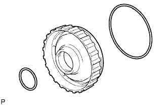
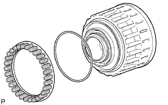
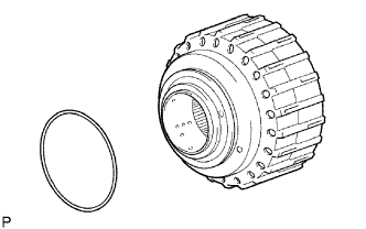
REMOVE REVERSE CLUTCH PISTON SUB-ASSEMBLY
-
Remove the reverse clutch piston sub-assembly from the clutch drum sub-assembly.
-
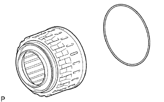
Remove the O-ring from the reverse clutch piston sub-assembly.
-
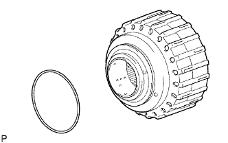
Remove the O-ring from the clutch drum sub-assembly.
-
-
REMOVE DIRECT CLUTCH PISTON SUB-ASSEMBLY
-
Place SST on the direct clutch piston, and compress the return spring with a press.
- SST
- 09320-89010
- 09350-30020 ( 09350-07070 )
-
Using 2 screwdrivers, remove the direct clutch piston sub-assembly from the clutch drum.
-
Remove the O-ring from the clutch drum.
-
Remove the No. 2 clutch balancer and direct clutch return spring sub-assembly from the direct clutch piston sub-assembly.
-
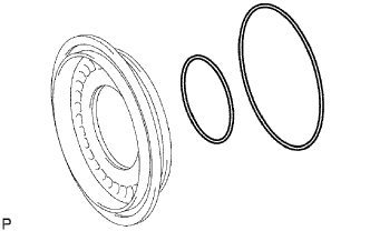
Remove the 2 O-rings from the direct clutch piston sub-assembly.
-
-
INSPECT DIRECT CLUTCH RETURN SPRING SUB-ASSEMBLY
-
Using a vernier caliper, measure the free length of the spring together with the spring seat.
Standard free length 19.51 mm (0.768 in.)
-