АВТОМАТИЧЕСКАЯ ТРАНСМИССИЯ В СБОРЕ УСТАНОВКА
-
INSPECT TORQUE CONVERTER CLUTCH ASSEMBLY
-
Inspect the torque converter clutch assembly Click here.
-
-
INSTALL TORQUE CONVERTER CLUTCH ASSEMBLY
-
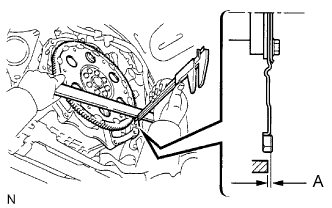
Install the torque converter clutch to the automatic transmission.
-
Using a vernier caliper and straightedge, measure dimension A between the transmission and the end surface of the drive plate.
Standard dimension A = 22.28 mm (0.8772 in.) -
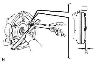
Using a vernier caliper and straightedge, measure dimension B shown in the illustration. Check that B is greater than A.
Standard dimension B = A + 1.00 mm (0.0394 in.) or more
-
-
INSTALL TRANSFER ASSEMBLY
-
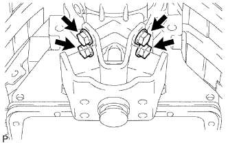
Установите раздаточную коробку на трансмиссию.
-
Установите 2 зажима и вверните 8 болтов.
- Torque:
- 24 Н*м { 244 кгс*см, 17 фунт-сила-футов }
-
-
INSTALL AUTOMATIC TRANSMISSION ASSEMBLY
-
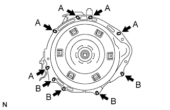
Install the transmission to the engine with the 9 bolts.
- Torque:
- 71 N*m { 720 kgf*cm, 53 ft.*lbf, for bolt A }
- 37 N*m { 380 kgf*cm, 27 ft.*lbf, for bolt B }
-
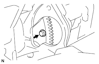
Hold the crankshaft pulley bolt with a wrench and install the 6 torque converter clutch mounting bolts.
- Torque:
- 48 N*m { 489 kgf*cm, 35 ft.*lbf }
Tech Tips
First install the black bolt, and then the other 5 bolts.
-
-
INSTALL FLYWHEEL HOUSING SIDE COVER
-
INSTALL STARTER ASSEMBLY
-
Install starter assembly Click here.
-
-
CONNECT WIRE HARNESS
-
CONNECT CONNECTOR
-
Transmission side:
Connect the connectors.
-
Connect the park/neutral position switch connector.
-
Connect the transmission wire connector.
-
Connect the 2 speed sensor connectors.
-
-
Transfer side:
Connect the connectors.
-
Connect the No. 1 indicator switch connector.
-
Connect the No. 2 indicator switch connector.
-
Connect the speed sensor connector.
-
-
-
INSTALL NO. 1 ENGINE MOUNTING INSULATOR REAR
-
Install the engine mounting insulator to the transmission with the 4 bolts.
- Torque:
- 65 N*m { 663 kgf*cm, 48 ft.*lbf }
-
-
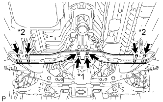
INSTALL NO. 3 FRAME CROSSMEMBER SUB-ASSEMBLY
-
*1: Install the 4 set bolts of the engine mounting insulator.
- Torque:
- 27 N*m { 275 kgf*cm, 20 ft.*lbf }
-
*2: Install the frame crossmember with the 4 bolts and 4 nuts.
- Torque:
- 50 N*m { 510 kgf*cm, 37 ft.*lbf }
-
-
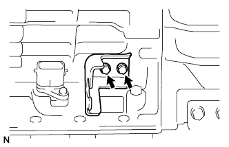
INSTALL NO. 1 TRANSMISSION CONTROL CABLE BRACKET
-
Install the control cable bracket with the 2 bolts.
- Torque:
- 28 N*m { 286 kgf*cm, 21 ft.*lbf }
-
-
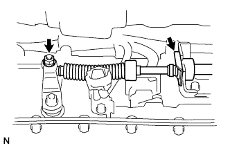
INSTALL TRANSMISSION CONTROL CABLE ASSEMBLY
-
Connect the control cable with the clip.
-
Connect the control cable with the nut.
- Torque:
- 14 N*m { 143 kgf*cm, 10 ft.*lbf }
-
-
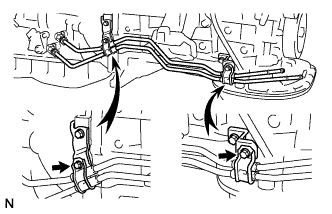
INSTALL OIL COOLER TUBE
-
Loosely install the tip of the oil cooler tube inlet to the automatic transmission by hand.
-
Loosely install the tip of the oil cooler tube outlet to the automatic transmission by hand.
-
Install the 2 clamps with the 2 bolts.
- Torque:
- 5.0 N*m { 50 kgf*cm, 43 in.*lbf }
-
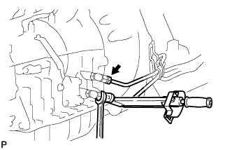
Using a union nut wrench, tighten the oil cooler inlet and outlet tubes.
- Torque:
- 34 N*m { 346 kgf*cm, 25 ft.*lbf }
Note
Use the formula to calculate special torque values for situations where a union nut wrench is combined with a torque wrench Click here.
-
-
INSTALL EXHAUST MANIFOLD SUB-ASSEMBLY RH
-
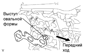
Set a new gasket to the RH cylinder head with the oval shape facing forward.
Note
Be careful of the installation direction.
-
Install the exhaust manifold with the 6 nuts. Uniformly tighten the nuts in several passes.
- Torque:
- 21 N*m { 214 kgf*cm, 15 ft.*lbf }
-
Connect the A/F sensor connector.
-
-
INSTALL EXHAUST MANIFOLD SUB-ASSEMBLY LH
-
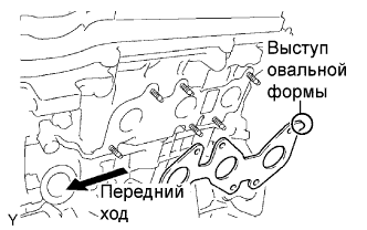
Set a new gasket to the LH cylinder head with the oval shape facing backward.
Note
Be careful of the installation direction.
-
Install the exhaust manifold with the 6 nuts. Uniformly tighten the nuts in several passes.
- Torque:
- 21 N*m { 214 kgf*cm, 15 ft.*lbf }
-
Connect the A/F sensor connector.
-
-
INSTALL NO. 2 MANIFOLD STAY
-
Install the manifold stay with the 3 bolts.
- Torque:
- 40 N*m { 408 kgf*cm, 30 ft.*lbf }
-
-
INSTALL MANIFOLD STAY

-
Install the manifold stay with the 3 bolts.
- Torque:
- 40 N*m { 408 kgf*cm, 30 ft.*lbf }
-
-
INSTALL REAR PROPELLER SHAFT ASSEMBLY
-
Install the rear propeller shaft Click here.
-
-
INSTALL FRONT PROPELLER SHAFT ASSEMBLY
-
Install the front propeller shaft Click here.
-
-
INSTALL EXHAUST PIPE
-
Install the exhaust pipe Click here.
-
-
CONNECT HEATED OXYGEN SENSOR
-
INSTALL TRANSFER CASE LOWER PROTECTOR
-
Install the protector with the 4 bolts.
- Torque:
- 18 N*m { 283 kgf*cm, 13 ft.*lbf }
-
-
CONNECT CABLE TO NEGATIVE BATTERY TERMINAL
-
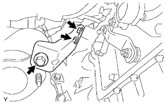
INSTALL TRANSFER HIGH AND LOW SHIFT LEVER ASSEMBLY
-
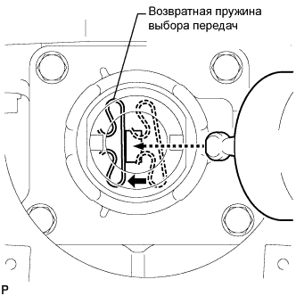
While pushing the select return spring to the left with the end of the transfer high and low shift lever, insert the end of the shift lever into the shift fork.
-
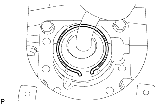
While holding down the shift lever cap, install the snap ring to install the transfer high and low shift lever.
-
Return the transfer front drive shift boot to its original position.
-
-
INSTALL SHIFT LEVER BOOT ASSEMBLY
-
Install the shift lever boot with the 4 screws.
-
-
INSTALL CONSOLE BOX ASSEMBLY
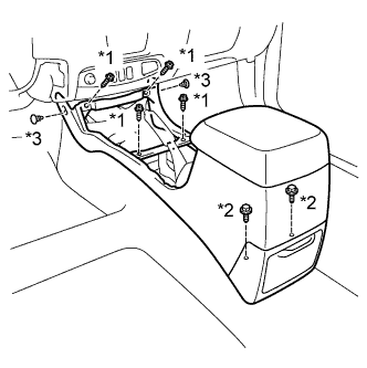
Обозначения на рисунке *1 Винт *2 Болт *3 Фиксатор
-
Установите вещевой ящик в облицовке туннеля пола и закрепите его 4 винтами и 2 болтами.
-
Установите 2 фиксатора.
-
-
INSTALL UPPER CONSOLE PANEL SUB-ASSEMBLY
-
Установите верхнюю облицовку панели пола и закрепите ее 12 захватами.
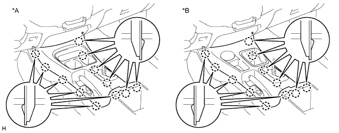
Обозначения на рисунке *A Для моделей с приводом на одну ось *B Для моделей с полным приводом
-
-
INSTALL PARKING BRAKE HOLE COVER SUB-ASSEMBLY
-
Введите в зацепление 4 захвата, чтобы установить крышку отверстия стояночного тормоза.
-
-
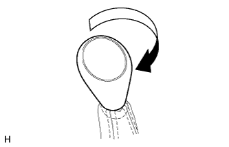
INSTALL SHIFT LEVER KNOB SUB-ASSEMBLY
-
Установите рукоятку рычага переключения передач и поверните ее в направлении, указанном стрелкой.
-
-
ADD TRANSFER OIL
-
Снимите пробку картера (наливной горловины) и прокладку.
-
Убедитесь, что уровень масла на 0–5,0 мм (0–0,197 дюйма) ниже нижней кромки отверстия для пробки (наливной горловины) картера.
Note
-
Добавляйте масло медленно.
-
Добавляйте масло понемногу за шаг, делая перерывы между шагами в несколько минут.
-
-
Подождите примерно 5 минут и проверьте, не изменится ли уровень масла.
-
Установите новую прокладку и затяните пробку картера (наливной горловины).
- Torque:
- 37 Н*м { 377 кгс*см, 27 фунт-сила-футов }
-
-
ADD AUTOMATIC TRANSMISSION FLUID
-
Add automatic transmission fluid Click here.
-
-
ADJUST AUTOMATIC TRANSMISSION FLUID
-
Adjust the automatic transmission fluid Click here.
-
-
INSPECT SHIFT LEVER POSITION
-
Inspect the shift lever position Click here.
-
-
PERFORM INITIALIZATION
-
Perform initialization Click here.
Note
Certain systems need to be initialized after disconnecting and reconnecting the cable from the negative (-) battery terminal.
-
-
CHECK FOR EXHAUST GAS LEAKS
-
INSTALL NO. 2 ENGINE UNDER COVER
- Torque:
- 28 N*m { 285 kgf*cm, 21 ft.*lbf }
-
INSTALL NO. 1 ENGINE UNDER COVER
- Torque:
- 28 N*m { 285 kgf*cm, 21 ft.*lbf }