БЛОК АВТОМАТИЧЕСКОЙ ТРАНСМИССИИ ПРОВЕРКА

-
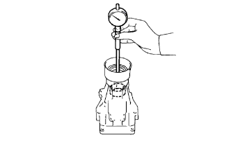
INSPECT EXTENSION HOUSING SUB-ASSEMBLY
-
Using a cylinder gauge, measure the inside diameter of the extension housing bush.
Maximum inside diameter 40.02 mm (1.5756 in.) If the inside diameter is greater than the maximum, replace the extension housing.
-
-
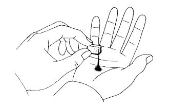
INSPECT AUTOMATIC TRANSMISSION OIL PAN SUB-ASSEMBLY
-
Remove the magnets and use them to collect steel particles.
-
Carefully look at the foreign matter and particles in the pan and on the magnets to anticipate the type of wear you will find in the transmission.
-
Steel (magnetic): bearing, gear and clutch plate wear.
-
Brass (non-magnetic): bush wear.
-
-
-
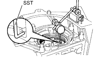
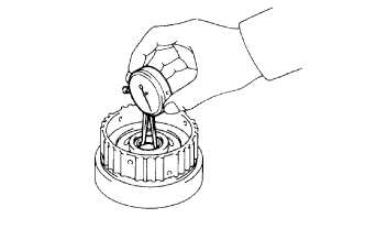
INSPECT OVERDRIVE BRAKE PISTON
-
Place SST and a dial indicator onto the overdrive brake piston.
- SST
- 09350-30020 ( 09350-06120 )
-
Measure the stroke while applying and releasing compressed air (392 kPa (4.0 kgf/cm2, 57 psi)).
Standard piston stroke 1.75 to 2.05 mm (0.0689 to 0.0807 in.) If the piston stroke is not as specified, parts may have been assembled incorrectly. Check and reassemble again.
Tech Tips
-
If the piston stroke is still outside the standard even after reassembly, select another flange.
-
There are 7 different thicknesses for the flange.
Standard flange thickness No. Specified Condition No. Specified Condition 77 3.3 mm (0.130 in.) 81 3.8 mm (0.150 in.) 78 3.5 mm (0.138 in.) 82 3.9 mm (0.154 in.) 79 3.6 mm (0.142 in.) 83 4.0 mm (0.157 in.) 80 3.7 mm (0.146 in.) - - -
-
-
INSPECT FRONT PLANETARY RING GEAR
-
Using a dial indicator, measure the inside diameter of the planetary ring gear bush.
Maximum inside diameter 24.65mm (0.9705 in.) If the inside diameter is greater than the maximum, replace the planetary ring gear.
-
-
INSPECT FRONT PLANETARY PINION GEAR THRUST CLEARANCE

-
Using a feeler gauge, measure the pinion gear thrust clearance.
Standard clearance 0.20 to 0.60 mm (0.0079 to 0.0236 in.) Maximum clearance 0.65 mm (0.0256 in.) If the clearance is greater than the maximum, replace the planetary gear.
-
-
INSPECT PACK CLEARANCE OF 1ST AND REVERSE BRAKE
-
Using a feeler gauge, measure the clearance between the plate and 2nd brake drum.
Standard clearance 0.70 to 1.22 mm (0.0276 to 0.048 in.) If the clearance is not as specified, select another flange.
Tech Tips
There are 8 different thicknesses for the flange.
Standard flange thickness No. Specified Condition No. Specified Condition 67 5.4mm (0.213 in.) 52 4.6 mm (0.181 in.) 66 5.2 mm (0.205 in.) 53 4.4 mm (0.173 in.) 50 5.0 mm (0.197 in.) 54 4.2 mm (0.165 in.) 51 4.8 mm (0.189 in.) 55 4.0 mm (0.157 in.)
-
-
INSPECT PACK CLEARANCE OF 2ND BRAKE
-
Using a feeler gauge, measure the clearance between the snap ring and flange.
Standard clearance 0.62 to 1.98 mm (0.0244 to 0.0780 in.) If the clearance is not as specified, inspect the discs.
-
-
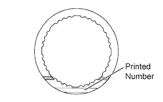
INSPECT 1ST AND REVERSE BRAKE CLUTCH DISC
-
Replace all discs if one of the following problems is present: 1) a disc, plate or flange is worn or burnt, 2) the lining of a disc is peeled off or discolored, or 3) grooves or printed numbers have even a little bit of damage.
Note
Before assembling new discs, soak them in ATF for at least 15 minutes.
-
-
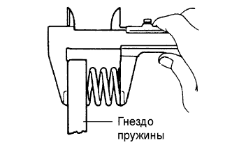
INSPECT 1ST AND REVERSE BRAKE RETURN SPRING SUB-ASSEMBLY
-
Using a vernier caliper, measure the free length of the spring together with the spring seat.
Standard free length 12.9 mm (0.508 in.) If the length is not as specified, replace the spring sub-assembly.
-
-
INSPECT TRANSMISSION CASE BUSHING
-
Using a cylinder gauge, measure the inside diameter of the transmission case rear bush.
Maximum inside diameter 38.19 mm (1.5035 in.) If the inside diameter is greater than the maximum, replace the transmission case.
-
-
INSPECT PISTON STROKE OF 1ST AND REVERSE BRAKE
-
Make sure the 1st and reverse brake pistons move smoothly when compressed air is applied into the transmission case.
-
-
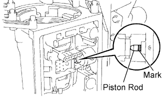
INSPECT PISTON STROKE OF 2ND COAST BRAKE
-
Place a mark on the 2nd coast brake piston rod.
-
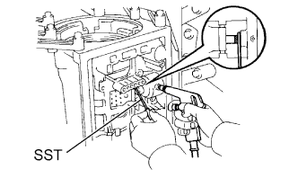
Using SST, measure the stroke while applying and releasing compressed air (392 kPa (4.0 kgf/cm2, 57 psi)).
- SST
- 09240-00020
If the stroke is not as specified, replace the brake band with a new one.
-
-
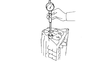
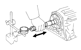
INSPECT OUTPUT SHAFT
-
Using a dial indicator, measure the end play of the output shaft with hand.
Standard end play 0.30 to 1.04 mm (0.0118 to 0.0409 in.) If the end play is not as specified, check for an improper installation.
-
Check that the output shaft rotates smoothly.
-
-
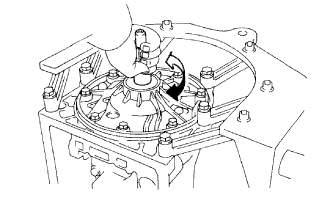
INSPECT INPUT SHAFT SUB-ASSEMBLY
-
Make sure the input shaft rotates smoothly.
-
-
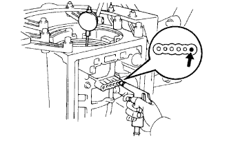
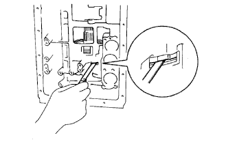
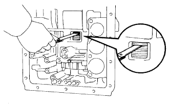
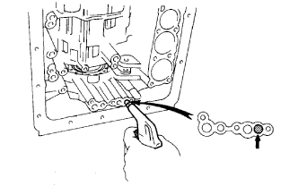
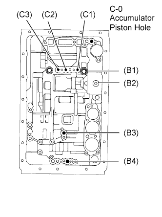
CHECK INDIVIDUAL PISTON OPERATION
-
Check the operating sound while applying compressed air into the oil hole indicated in the illustration.
Tech Tips
When inspecting the overdrive direct clutch, check with the C-0 accumulator piston hole closed.
If there is no sound, disassemble and check the parts installation condition.
-
Overdrive direct clutch (C1)
-
Direct clutch (C2)
-
Forward clutch (C3)
-
Overdrive brake (B1)
-
2nd coast brake (B2)
-
2nd brake (B3)
-
1st and reverse brake (B4)
-
-