ТОПЛИВНЫЙ БАК УСТАНОВКА

-
INSTALL FUEL TANK TO FILLER PIPE HOSE
-
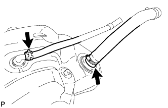
Install the fuel tank to filler pipe hose to the fuel tank.
-
-
INSTALL FUEL TANK BREATHER HOSE
-
Install the fuel tank breather hose to the fuel tank.
-
-
INSTALL FUEL SUCTION WITH PUMP AND GAUGE TUBE ASSEMBLY
-
Set the fuel pump gauge retainer on the fuel tank. While holding the fuel suction with pump and gauge tube, tighten the retainer one complete turn by hand.
-
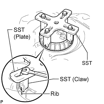
Temporarily install SST (plate and 4 claws) to the fuel pump gauge retainer.
- SST
- 09808-14030
Tech Tips
-
Be sure to use 4 SST (claws) as shown in the illustration.
-
Engage SST (claws) securely with the fuel pump gauge retainer ribs to secure SST.
-
While pressing SST (claws) against the fuel pump gauge retainer ribs securely, install the 4 bolts.
Tech Tips
Install SST while pressing SST (claws) against the fuel pump gauge retainer (toward the center of SST).
-
Install SST (handle).
-
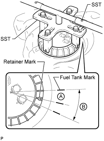
Using SST, tighten the retainer until the mark on the retainer aligns with mark A on the fuel tank as shown in the illustration.
- SST
- 09808-14030
Note
-
Do not use any tools other than those specified in this operation. Damage to the fuel pump gauge retainer or fuel tank may result.
-
Do not press down on SST excessively as this may make the fuel pump gauge retainer hard to rotate, and may damage components.
-
Make sure to rotate SST (handle) horizontally. If SST (handle) is rotated at an angle, SST may come off.
-
Do not spin SST too fast or use an impact wrench as this may result in damage to components.
-
If SST comes off of the fuel pump gauge retainer, loosen SST (bolts) and reinstall SST.
Tech Tips
-
If the alignment is difficult, make sure the mark on the retainer is within range B on the fuel tank.
-
Lightly press down on SST to prevent it from separating from the fuel pump gauge retainer. While pressing SST, rotate the handle slowly to tighten the fuel pump gauge retainer.
-
The tips of SST (claws) can be fitted onto the ribs of the fuel pump gauge retainer.
-
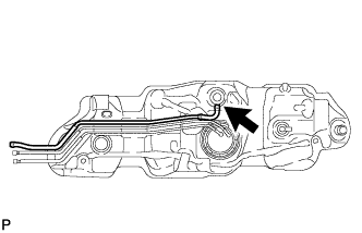
Install the fuel tank return tube and fuel tank main tube to the fuel tank.
-
Install the 2 fuel tank tubes with the 2 tube joint clips.
Note
-
Check that there are no scratches or foreign objects on the connecting parts.
-
Check that the fuel tube joints are inserted securely.
-
Check that the tube joint clips are on the collars of the fuel tube joints.
-
After installing the tube joint clips, check that the fuel tube joints have not been pulled off.
-
-
-
INSTALL NO. 1 FUEL EVAPORATION TUBE SUB-ASSEMBLY
-
Install the No. 1 fuel evaporation tube.
-
-
INSTALL FUEL TANK CUSHION
-
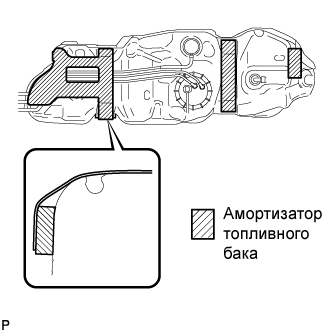
Install 4 new fuel tank cushions.
-
-
INSTALL NO. 1 FUEL TANK PROTECTOR SUB-ASSEMBLY
-
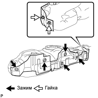
Install the No. 1 fuel tank protector with the 5 clips and 2 nuts.
- Torque:
- 6.0 N*m { 61 kgf*cm, 53 in.*lbf }
-
-
INSTALL FUEL TANK ASSEMBLY
-
Set the fuel tank on a transmission jack and raise the fuel tank.
Note
Do not allow the fuel tank to contact the vehicle, especially the differential.
-
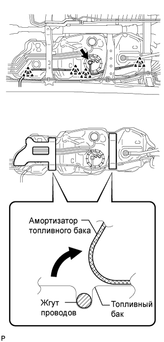
Fold back the 2 cushions.
-
Attach the wire harness to the 4 clamps and connect the fuel pump and sender gauge connector.
Note
Be careful not to cut the wiring.
-
Install the 3 fuel tank bands with the 3 pins and 3 clips.
-
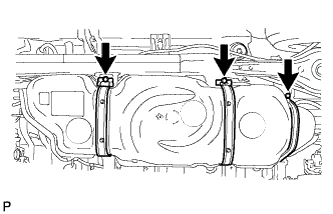
Connect the 3 fuel tank bands with the 3 bolts.
- Torque:
- 61 N*m { 622 kgf*cm, 45 ft.*lbf }
-
-
INSTALL FUEL TANK FILLER PIPE
-
Install the filler pipe with the bolt and nut.
- Torque:
- 19 N*m { 194 kgf*cm, 14 ft.*lbf }
-
-
CONNECT FUEL TANK TO FILLER PIPE HOSE
-
Connect the fuel tank to filler pipe hose to the fuel tank filler pipe.
-
-
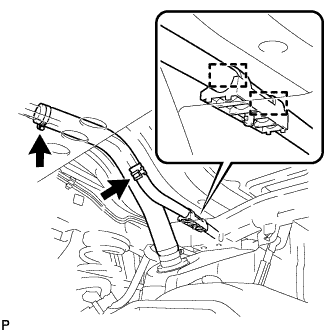
CONNECT FUEL TANK BREATHER HOSE
-
Attach the breather hose to the 2 clamps.
-
Connect the fuel tank breather hose to the fuel tank filler pipe.
-
-
CONNECT FUEL TANK MAIN TUBE SUB-ASSEMBLY AND FUEL TANK RETURN TUBE
Note
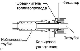
Before installing the tube connectors to the pipes, check the connectors for damage and foreign matter.
-
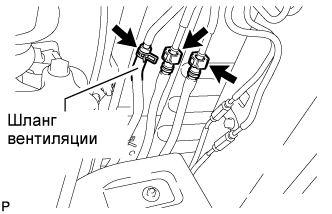
Connect the fuel tank return tube connector to the pipe. Then connect the fuel tank main tube connector to the pipe. Push the 2 tube connectors into the pipe until the tube connector makes a "click" sound.
Note
-
-
Check if there is any damage or foreign objects on the connected part of the fuel pipe.
-
After connecting, check that the pipe and connector are securely connected by pulling them.
-
-
Connect the vent line hose to the fuel pipe.
-
-
INSTALL NO. 3 FUEL TUBE CLAMP
-
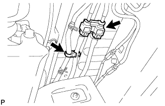
Install the 2 tube clamps to the fuel tube.
-
-
INSTALL FUEL TANK PROTECTOR
-
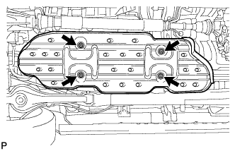
Install the fuel tank protector with the 4 nuts.
- Torque:
- 20 N*m { 204 kgf*cm, 15 ft.*lbf }
-
-
INSTALL FUEL TANK CAP ASSEMBLY
-
CONNECT CABLE TO NEGATIVE BATTERY TERMINAL
Note
When disconnecting the cable, some systems need to be initialized after the cable is reconnected Click here.
-
CHECK FOR FUEL LEAKS
-
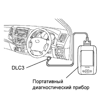
Connect the intelligent tester to the DLC3.
-
Turn the ignition switch ON.
Note
Do not start the engine.
-
Push the intelligent tester main switch ON.
-
To perform the Active Test, enter the following menus: Powertrain / Engine and ECT / Active Test / Control the Fuel Pump / Speed.
-
-
Check the fuel pump operation.
-
Check for pressure in the fuel inlet tube from the fuel line. Check that the sound of fuel flowing in the fuel tank can be heard.
If there is no sound, check the integration relay, fuel pump, ECM and wiring connector.
-
-
Check for fuel leaks.
-
Check that there are no fuel leaks after performing maintenance anywhere on the system.
If there are fuel leaks, repair or replace the leaking parts.
-
-