ДАТЧИК СОСТАВА ТОПЛИВОВОЗДУШНОЙ СМЕСИ ПРОВЕРКА БЕЗ СНЯТИЯ С АВТОМОБИЛЯ
-
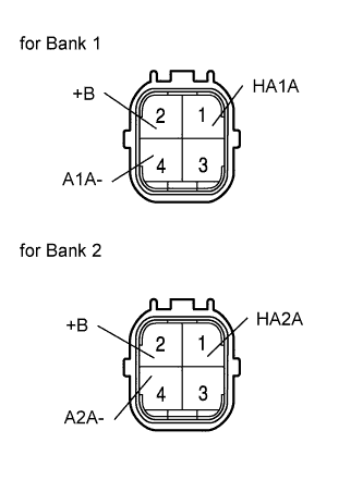
INSPECT AIR FUEL RATIO SENSOR (for Sensor 1)
-
Using an ohmmeter, measure the resistance of the sensor.
Standard resistance Tester Connection Specified Condition 1 (HA1A) - 2 (+B) 1.8 to 3.4 Ω at 20°C (68°F) 1 (HA1A) - 4 (A1A-) 10 kΩ or higher 1 (HA2A) - 2 (+B) 1.8 to 3.4 Ω at 20°C (68°F) 1 (HA2A) - 4 (A2A-) 10 kΩ or higher If the result is not as specified, replace the sensor.
-
-
INSPECT AIR FUEL RATIO COMPENSATION SYSTEM
-
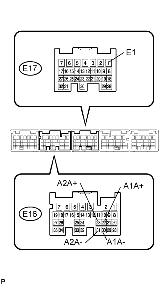
Measure the voltage between the terminals of the ECM.
Standard voltage Tester Connection Condition Specified Condition E16-22 (A1A+) - E17-1 (E1) Ignition switch ON 3.3 V E16-23 (A2A+) - E17-1 (E1) Ignition switch ON 3.0 V E16-30 (A1A-) - E17-1 (E1) Ignition switch ON 3.3 V E16-31 (A2A-) - E17-1 (E1) Ignition switch ON 3.0 V Note
Connect test leads from the backside of the ECM connector with the ECM connected.
Tech Tips
Voltage between the terminals of the ECM is kept constant regardless of the voltage of the A/F sensor.
-
Connect the intelligent tester to the DLC3.
-
Select "DATA MONITOR" - "A/FS B1 S1", "A/FS B2 S1" and "O2S B1 S2" to display the monitor.
-
Warm up the A/F sensor with the engine speed at 2,500 rpm for approximately 2 minutes.
-

Keep the engine speed at 2,500 rpm and confirm that the displays of "A/FS B1S1" and "A/FS B2 S1" are similar to the illustration.
Tech Tips
-
The illustration differs from the real display.
-
Only the intelligent tester displays the waveform of the A/F sensor.
-
-
Confirm that the display of "O2S B1 S2" changes between 0 to 1 V with the engine speed at 2,500 rpm.
-