РЕГУЛЯТОР ДАВЛЕНИЯ В ТОПЛИВНОЙ СИСТЕМЕ УСТАНОВКА
-
INSTALL FUEL PRESSURE REGULATOR ASSEMBLY
-
Install the vacuum hose.
-
Apply a light coat of spindle oil or gasoline to a new O-ring and install it to the fuel pressure regulator.
-
Install the fuel pressure regulator with the 2 bolts.
- Torque:
- 9.0 N*m { 92 kgf*cm, 80 in.*lbf }
-
-
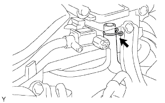
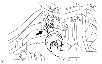
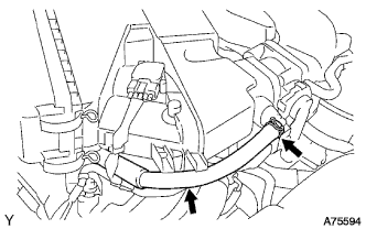
CONNECT NO. 2 FUEL PIPE SUB-ASSEMBLY
-
Connect the fuel pipe.
-
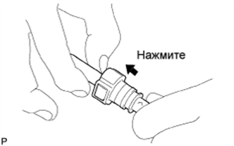
Check that there is no damage or contamination in the connected part of the pipe.
-
Align the axis of the connector with the axis of the pipe. Push the pipe into the connector until the connector makes a "click" sound. If the connection is tight, apply a small amount of fresh engine oil on the tip of the pipe.
-
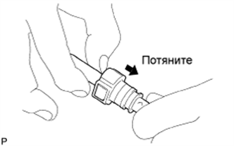
After completing the connection, try to pull apart the pipe and the connector and confirm that they are securely connected.
-
-
Install the fuel pipe clamp.
-
-
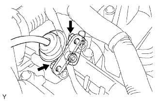
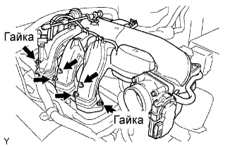
INSTALL INTAKE AIR SURGE TANK
-
Install a new gasket and the surge tank with the 2 nuts.
- Torque:
- 28 N*m { 286 kgf*cm, 21 ft.*lbf }
-
Using an 8 mm hexagon wrench, install the 4 bolts.
- Torque:
- 28 N*m { 286 kgf*cm, 21 ft.*lbf }
-
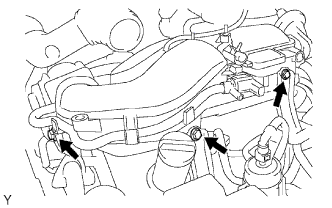
Install the 3 upper bolts which are used to secure the 2 surge tank stays and throttle body bracket.
- Torque:
- 21 N*m { 214 kgf*cm, 16 ft.*lbf }
-
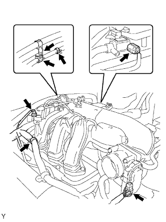
Install the 3 wire harness clamps and hose clamp.
-
Connect the throttle position sensor and control motor connector.
-
Connect the purge VSV connector.
-
Connect the VSV (for ACIS) connector.
-
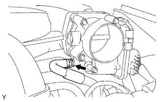
Connect the No. 1 ventilation hose.
-
Connect the purge line hose.
-
Connect the No. 4 water by-pass hose.
-
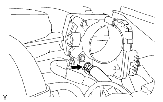
Connect the No. 5 water by-pass hose.
-
-
INSTALL AIR CLEANER ASSEMBLY
- Torque:
- 8.0 N*m { 82 kgf*cm, 71 in.*lbf }
-
CONNECT NO. 2 VENTILATION HOSE
-
INSTALL V-BANK COVER
-
Install the cover with the 2 nuts.
- Torque:
- 7.5 N*m { 76 kgf*cm, 66 in.*lbf }
-
-
CONNECT CABLE TO NEGATIVE BATTERY TERMINAL
-
PERFORM INITIALIZATION
-
Perform initialization Click here.
Note
Certain systems need to be initialized after disconnecting and reconnecting the cable from the negative (-) battery terminal.
-
-
CHECK FOR FUEL LEAKS
-
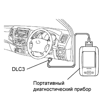
Connect the intelligent tester to the DLC3.
-
Turn the ignition switch ON.
Note
Do not start the engine.
-
Push the intelligent tester main switch ON.
-
To perform the Active Test, enter the following menus: Powertrain / Engine and ECT / Active Test / Control the Fuel Pump / Speed.
-
-
Check the fuel pump operation.
-
Check for pressure in the fuel inlet tube from the fuel line. Check that the sound of fuel flowing in the fuel tank can be heard.
If there is no sound, check the integration relay, fuel pump, ECM and wiring connector.
-
-
Check for fuel leaks.
-
Check that there are no fuel leaks after performing maintenance anywhere on the system.
If there are fuel leaks, repair or replace the leaking parts.
-
-