БЛОК ДВИГАТЕЛЯ РАЗБОРКА

Tech Tips
-
Thoroughly clean all parts to be assembled.
-
Before installing the parts, apply new engine oil to all sliding and rotating surfaces.
-
Replace all gaskets, O-rings and oil seals with new parts.
-
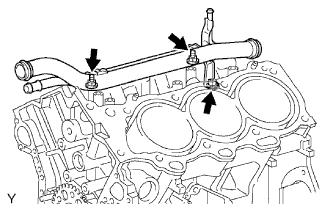
REMOVE NO. 1 ENGINE HANGER
-
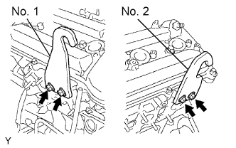
Remove the 2 bolts and No. 1 engine hanger.
-
-
REMOVE NO. 2 ENGINE HANGER
-
Remove the 2 bolts and No. 2 engine hanger.
-
-
REMOVE OIL DIPSTICK GUIDE
-
Remove the bolt and pull out the dipstick.
-
Remove the O-ring from the oil dipstick guide.
-
-
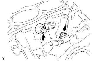
REMOVE CYLINDER BLOCK WATER DRAIN COCK
-
Remove the 2 water drain cocks.
-
-
REMOVE VVT SENSOR
-
Remove the 2 bolts and 2 sensors.
-
-
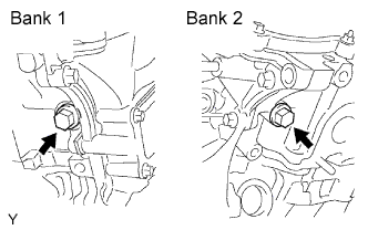
REMOVE CRANKSHAFT POSITION SENSOR
-
Remove the bolt and crankshaft position sensor.
-
-
REMOVE OIL CONTROL VALVE FILTER
-
Remove the plug, filter and gasket from each cylinder head.
-
-
REMOVE CYLINDER HEAD COVER RH
-
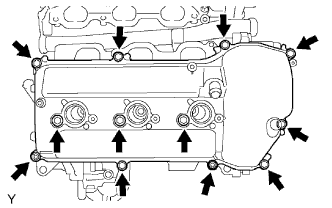
Remove the 10 bolts, 3 seal washers, 2 nuts, head cover and gasket.
-
-
REMOVE CYLINDER HEAD COVER LH
-
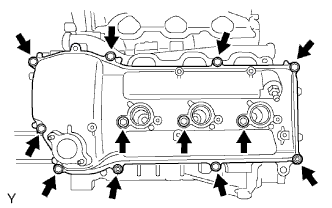
Remove the 10 bolts, 3 seal washers, 2 nuts, cylinder head cover and gasket.
-
Remove the ventilation valve from the cylinder head cover.
-
-
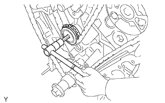
REMOVE CRANKSHAFT PULLEY
-
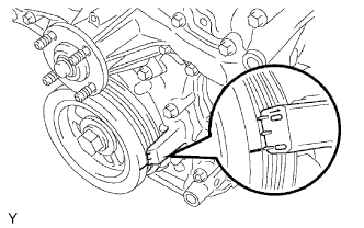
Turn the crankshaft pulley, and align its groove with timing mark 0 of the timing chain cover.
-
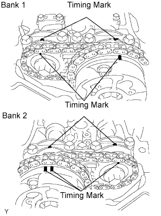
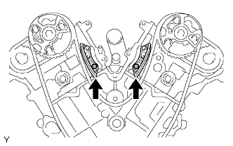
Check that the timing marks of the camshaft timing gears are aligned with the timing marks of the bearing cap as shown in the illustration.
If not, turn the crankshaft 1 revolution (360°) and align the timing marks as described above.
-
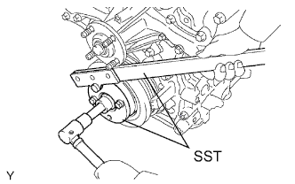
Using SST, hold the crankshaft pulley and loosen the pulley set bolt.
- SST
- 09213-54015 ( 91651-60855 )
- 09330-00021
-
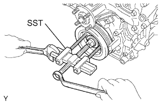
Using the pulley set bolt and SST, remove the crankshaft pulley.
- SST
- 09950-50013 ( 09951-05010, 09952-05010, 09953-05020, 09954-05030 )
-
-
REMOVE OIL PAN DRAIN PLUG
-
Remove the drain plug and gasket.
-
-
REMOVE NO. 2 OIL PAN
-
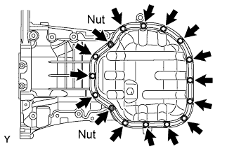
Remove the 14 bolts and 2 nuts.
-
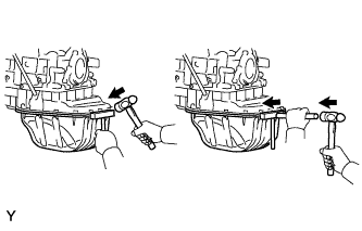
Insert the blade of an oil pan seal cutter between the oil pan and No. 2 oil pan, cut through the applied sealer and remove the No. 2 oil pan.
Note
-
Be careful not to damage the contact surface of the No. 2 oil pan and No. 1 oil pan.
-
Be careful not to damage the No. 2 oil pan flange.
-
-
-
REMOVE OIL STRAINER
-
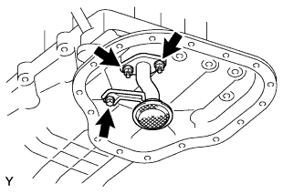
Remove the bolt, 2 nuts, oil strainer and gasket.
-
-
REMOVE NO. 1 OIL PAN
-
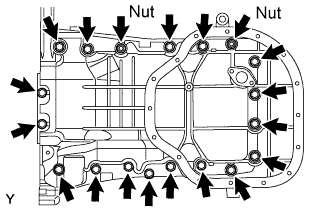
Remove the 17 bolts and 2 nuts.
-
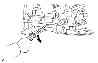
Using a screwdriver, remove the oil pan by prying between the oil pan and cylinder block.
Note
Be careful not to damage the contact surfaces of the cylinder block and oil pan.
-
Remove the O-ring from the timing chain cover.
-
-
REMOVE WATER PUMP
-
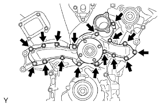
Remove the 17 bolts, water pump and gasket.
-
-
REMOVE TIMING CHAIN COVER
-
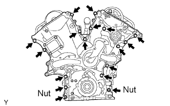
Remove the 15 bolts and 2 nuts.
-
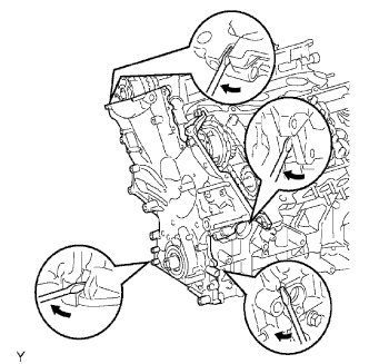
Remove the timing chain cover by prying the portions between the timing chain cover and cylinder head or cylinder block with a screwdriver.
Note
Be careful not to damage the contact surfaces of the timing chain cover, cylinder block and cylinder head.
-
Remove the O-ring from the LH cylinder head.
-
-
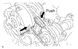
REMOVE NO. 1 CHAIN TENSIONER
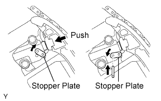
Note
-
Never rotate the crankshaft with the chain tensioner removed.
-
When rotating the camshaft with the timing chain removed, rotate the crankshaft counterclockwise 40° from the TDC before rotating it.
-
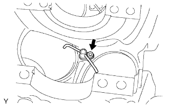
While rotating the stopper plate of the tensioner upward, push in the plunger of the chain tensioner as shown in the illustration.
-
While rotating the stopper plate of the tensioner downward, insert a pin of φ3.5 mm (0.138 in.) into the holes in the stopper plate and tensioner to fix the stopper plate.
-
Remove the 2 bolts and chain tensioner.
-
-
REMOVE CHAIN TENSIONER SLIPPER
-
REMOVE NO. 1 IDLE GEAR
-
Using a 10 mm hexagon wrench, remove the No. 2 idle gear shaft, No. 1 idle gear and No. 1 idle gear shaft.
-
-
REMOVE NO. 2 CHAIN VIBRATION DAMPER
-
Remove the 2 chain vibration dampers.
-
-
REMOVE CHAIN
-
REMOVE CRANKSHAFT TIMING SPROCKET
-
REMOVE NO. 1 CHAIN VIBRATION DAMPER
-
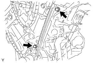
Remove the 2 bolts and No. 1 chain vibration damper.
-
-
REMOVE CAMSHAFT TIMING GEARS AND NO. 2 CHAIN (for Bank 1)
-
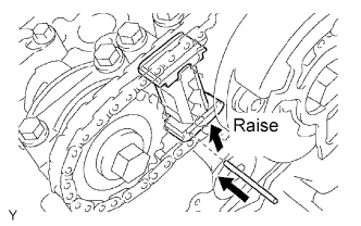
While raising up the No. 2 chain tensioner, insert a pin of φ1.0 mm (0.039 in.) into the hole to fix it.
-
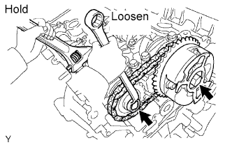
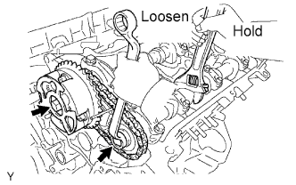
Hold the hexagonal portion of the camshaft with a wrench, and remove the 2 bolts, camshaft timing gear, camshaft timing gear assembly and No. 2 timing chain.
Note
-
Be careful not to damage the cylinder head and valve lifter with the wrench.
-
Do not disassemble the camshaft timing gear assembly.
-
-
-
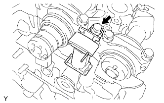
REMOVE NO. 2 CHAIN TENSIONER
-
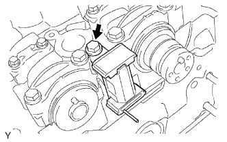
Remove the bolt and No. 2 chain tensioner.
-
-
REMOVE CAMSHAFT TIMING GEARS AND NO. 2 CHAIN (for Bank 2)
-
While pushing down the No. 3 chain tensioner, insert a pin of φ1.0 mm (0.039 in.) into the hole to fix it.
-
Hold the hexagonal portion of the camshaft with a wrench, and remove the 2 bolts, camshaft timing gear, camshaft timing gear assembly and No. 2 timing chain.
Note
-
Be careful not to damage the cylinder head and valve lifter with the wrench.
-
Do not disassemble the camshaft timing gear assembly.
-
-
-
REMOVE NO. 3 CHAIN TENSIONER
-
Remove the bolt and No. 3 chain tensioner.
-
-
REMOVE CAMSHAFT
Note
As the thrust clearance of the camshaft is small, the camshaft must be kept level while it is being removed. If the camshaft is not kept level, the portion of the cylinder head which receives the shaft thrust may crack or be damaged, causing the camshaft to seize or break. To avoid this, the following steps should be carried out.
-
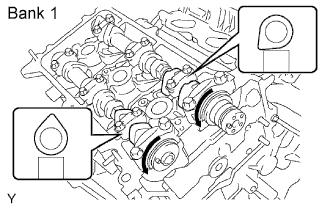
Remove the camshafts of the bank 1.
-
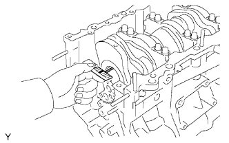
Rotate the camshafts counterclockwise using the hexagonal portion of each camshaft so that the cam lobes of the No. 1 cylinder are as shown in the illustration.
-
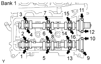
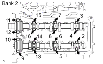
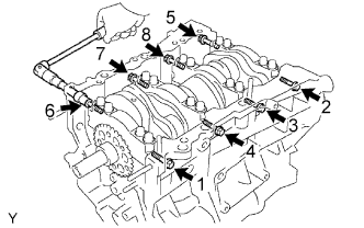
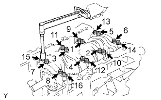
Uniformly loosen and remove the 16 bearing cap bolts in several passes, in the sequence shown.
-
Remove the 8 bearing caps and 2 camshafts.
-
-
Remove the camshafts of the bank 2.
-
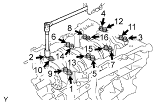
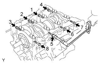
Uniformly loosen and remove the 16 bearing cap bolts in several passes, in the sequence shown.
-
Remove the 8 bearing caps and 2 camshafts.
-
-
-
REMOVE NO. 1 CAMSHAFT BEARING
-
REMOVE NO. 2 CAMSHAFT BEARING
-
REMOVE CYLINDER HEAD
-
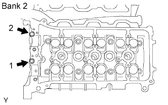
Remove the 2 cylinder head bolts on the LH cylinder head in several passes, in the sequence shown.
-
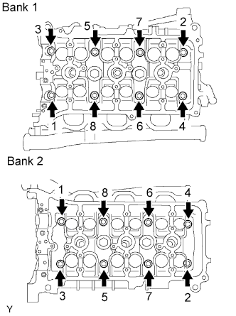
Using a 10 mm bi-hexagon wrench, uniformly loosen the 8 cylinder head bolts on each cylinder head in several passes in the sequence shown, then repeat for the other side as shown. Remove the 16 cylinder head bolts and plate washers.
Note
-
Be careful not to drop the plate washers into the cylinder head.
-
Head warpage or cracking could result from removing bolts in the incorrect order.
-
-
Lift the cylinder head from the dowels on the cylinder block, and place the 2 cylinder heads on wooden blocks on a bench.
Note
Be careful not to damage the contact surfaces of the cylinder head and cylinder block.
Tech Tips
If the cylinder head is difficult to lift off, pry between the cylinder head and cylinder block with a screwdriver.
-
Remove the bank 1 and bank 2 cylinder head gaskets.
-
-
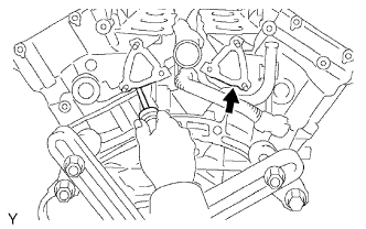
REMOVE NO. 1 WATER OUTLET PIPE
-
Separate the knock sensor wire.
-
Remove the bolt, 2 nuts and water outlet pipe.
-
-
REMOVE KNOCK SENSOR
-
Disconnect the 2 knock sensor connectors.
-
Remove the 2 bolts and 2 knock sensors.
-
-
REMOVE ENGINE REAR OIL SEAL RETAINER
-
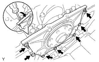
Remove the 5 bolts and 2 nuts.
-
Using a screwdriver, remove the oil seal retainer by prying the portions between the oil seal retainer and crankshaft bearing cap.
-
-
REMOVE VALVE LIFTER
Tech Tips
Arrange the valve lifter in the correct order.
-
REMOVE VALVE
Tech Tips
Arrange the valves, inner compression springs, valve spring retainers and valve spring retainer locks in the correct order.
-
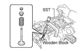
Place the cylinder head on a wooden block.
-
Using SST, compress the inner compression spring and remove the 2 valve spring retainer locks.
- SST
- 09202-70020 ( 09202-00010 )
-
Remove the valve, inner compression spring, valve spring and valve spring retainer.
-
-
REMOVE VALVE SPRING SEAT
-
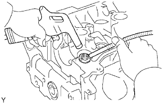
Using compressed air and a magnetic finger, remove the valve spring seat by blowing air.
-
-
REMOVE VALVE STEM OIL SEAL
-
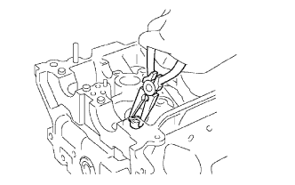
Using needle-nose pliers, remove the valve stem oil seal.
-
-
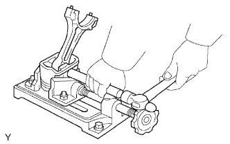
INSPECT CONNECTING ROD THRUST CLEARANCE
-
Using a dial indicator, measure the thrust clearance while moving the connecting rod back and forth.
Standard thrust clearance 0.15 to 0.30 mm (0.0059 to 0.0118 in.) Maximum thrust clearance 0.35 mm (0.0138 in.) If the thrust clearance is greater than the maximum, replace the connecting rod assembly. If necessary, replace the crankshaft.
-
-
INSPECT CONNECTING ROD OIL CLEARANCE
-
Check the matchmarks on the connecting rod and cap are aligned to ensure correct reassembly.
-
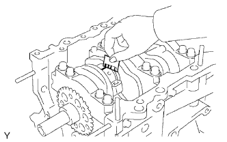
Using SST, remove the 2 connecting rod cap bolts.
- SST
- 09011-38121
-
Clean the crank pin, bearing and connecting rod.
-
Check the crank pin and bearing for pitting and scratches.
If the crank pin or bearing is damaged, replace the bearings. If necessary, replace the crankshaft.
-
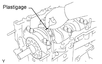
Lay a strip of Plastigage across the crank pin.
-
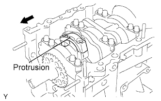
Check that the protrusion of the connecting rod cap is facing in the correct direction.
-
Apply a light coat of engine oil on the threads and under the heads of the connecting rod cap bolts.
-
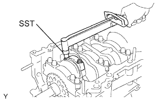
Using SST, tighten the bolts in several passes by the specified torque.
- SST
- 09011-38121
- Torque:
- 25 N*m { 250 kgf*cm, 18 ft.*lbf }
-
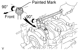
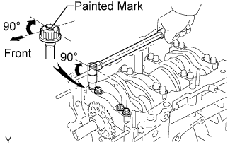
Mark the front side of each connecting cap bolt with paint.
-
Retighten the cap bolts by 90° as shown in the illustration.
Note
Do not turn the crankshaft.
-
Remove the 2 bolts, connecting rod cap and lower bearing.
-
Measure the Plastigage at its widest point.
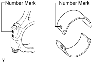
Standard oil clearance 0.026 to 0.046 mm (0.0010 to 0.0018 in.) Maximum oil clearance 0.066 mm (0.0025 in.) If replacing the bearing, replace it with one having the same number as marked on the connecting rod. There are 4 sizes of standard bearings, marked 1, 2, 3 and 4 accordingly.
Standard bearing center wall thickness Mark Specified Condition 1 1.484 to 1.487 mm (0.0584 to 0.0585 in.) 2 1.487 to 1.490 mm (0.0585 to 0.0587 in.) 3 1.490 to 1.493 mm (0.0587 to 0.0588 in.) 4 1.493 to 1.496 mm (0.0588 to 0.0589 in.) -
Completely remove the Plastigage.
-
-
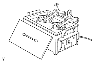
REMOVE PISTON WITH CONNECTING ROD
-
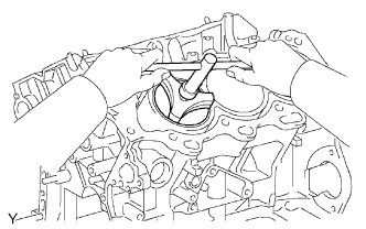
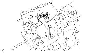
Using a ridge reamer, remove all the carbon from the top of the cylinder.
-
Push the piston, connecting rod assembly and upper bearing through the top of the cylinder block.
Tech Tips
-
Keep the bearings, connecting rod and cap together.
-
Arrange the piston and connecting rod assemblies in the correct order.
-
-
-
REMOVE PISTON RING SET
-
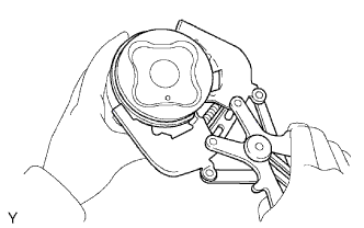
Using a piston ring expander, remove the 2 compression rings.
-
Remove the 2 side rails and oil ring by hand.
-
-
REMOVE PISTON WITH PIN
-
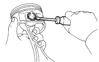
Using a small screwdriver, pry out the 2 snap rings.
-
Gradually heat the piston to approximately 80°C (176°F).
-
Using a plastic-faced hammer and brass bar, lightly tap out the piston pin and remove the connecting rod.
Tech Tips
-
The piston and pin are a matched set.
-
Arrange the pistons, pins, rings, connecting rods and bearings in the correct order.
-
-
-
INSPECT CRANKSHAFT THRUST CLEARANCE
-
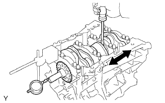
Using a dial indicator, measure the thrust clearance while prying the crankshaft back and forth with a screwdriver.
Standard thrust clearance 0.04 to 0.24 mm (0.0016 to 0.0094 in.) Maximum thrust clearance 0.30 mm (0.0118 in.) If the thrust clearance is greater than the maximum, replace the thrust washers as a set or a crankshaft.
Tech Tips
Thrust washer thickness: 1.93 to 1.98 mm (0.0760 to 0.0780 in.)
-
-
INSPECT CRANKSHAFT OIL CLEARANCE
-
Uniformly loosen and remove the 8 main bearing cap bolts and seal washers in several passes, in the sequence shown.
-
Uniformly loosen and remove the 16 main bearing cap bolts in several passes, in the sequence shown.
-
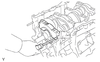
Using a screwdriver, pry out main bearing caps. Remove the 4 main bearing caps and lower bearings.
Note
-
Pry up the main bearing cap little by little on the right and the left by turns.
-
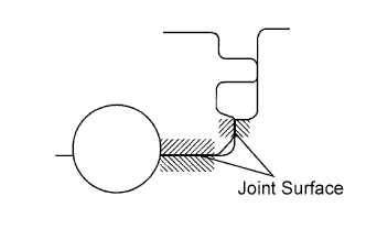
Be careful not to damage the joint surface of the cylinder block and the main bearing cap.
Tech Tips
-
Keep the lower bearing and cap together.
-
Be sure to arrange the bearing caps and lower thrust washers in such a way that they can be reinstalled exactly as before.
-
-
Lift out the crankshaft.
-
Remove the 2 upper thrust washers.
Tech Tips
-
Be sure to arrange the removed upper thrust washers in such a way that they can be reinstalled exactly as before.
-
Keep the upper bearings together with the cylinder block.
-
-
Clean each crankshaft journal and bearing.
-
Check each crankshaft journal and bearing for pitting and scratches.
If the journal or bearing is damaged, replace the bearings. If necessary, replace the crankshaft.
-
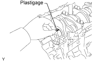
Lay a strip of Plastigage across each journal.
-
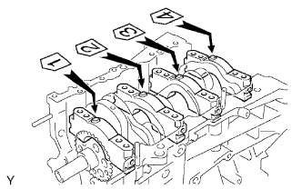
Examine the front marks and numbers, and install the bearing caps on the cylinder block.
-
Apply a light coat of engine oil on the threads and under the heads of the bearing cap bolts.
-
Temporarily install the 8 main bearing cap bolts to the inside positions.
-
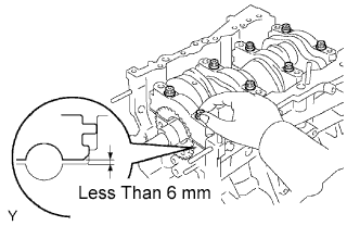
Insert the main bearing cap by hand until the clearance between the main bearing cap and the cylinder block is less than 6 mm (0.23 in.) by using the 2 internal bearing cap bolts as a guide.
-
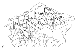
Using a plastic-faced hammer, lightly tap the bearing cap to ensure a proper fit.
-
Apply a light coat of engine oil on the threads and under the heads of the main bearing cap bolts.
-
Install and uniformly tighten the 16 main bearing cap bolts in several passes, in the sequence shown.
- Torque:
- 61 N*m { 622 kgf*cm, 45 ft.*lbf }
-
Mark the front side of the bearing cap bolts with paint.
-
Retighten the bearing cap bolts by 90° in the sequence shown.
-
Check that the painted mark is now at a 90° angle to the front.
Note
Do not turn the crankshaft.
-
Install and uniformly tighten the 8 main bearing cap bolts in several passes, in the sequence shown.
- Torque:
- 35 N*m { 357 kgf*cm, 26 ft.*lbf }
-
Remove the main bearing caps.
-
Measure the Plastigage at its widest point.
Standard oil clearance Standard oil clearance Maximum clearance 0.046 mm (0.0018 in.) If the oil clearance is greater than the maximum, replace the bearings. If necessary, replace the crankshaft.
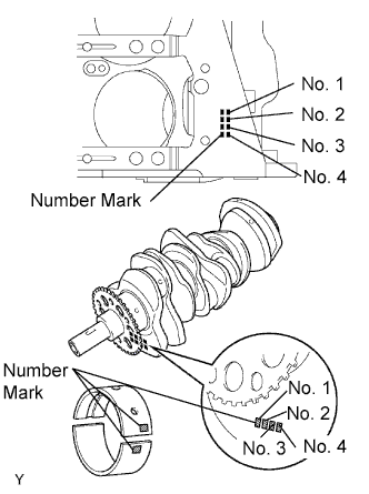
Using a bearing, replace it with one having the same number. If the number of the bearing cannot be determined, select the correct bearing by adding together the numbers imprinted on the cylinder block and crankshaft, then refer to the table below for the appropriate bearing number. There are 5 sizes of standard bearings, marked 1, 2, 3, 4 and 5 accordingly.
Journal bearing Cylinder block (A) + Crankshaft (B) 0 to 5 6 to 11 12 to 17 18 to 23 24 to 28 Use Bearing 1 2 3 4 5 Tech Tips
EXAMPLE
Cylinder block "11" (A) + Crankshaft "06" (B) = Total "17" (Use bearing "3")
Cylinder block main journal bore diameter (A) Mark Specified Condition 00 77.000 mm (3.0315 in.) 01 77.001 mm (3.0315 in.) 02 77.002 mm (3.0316 in.) 03 77.003 mm (3.0316 in.) 04 77.004 mm (3.0317 in.) 05 77.005 mm (3.0317 in.) 06 77.006 mm (3.0317 in.) 07 77.007 mm (3.0318 in.) 08 77.008 mm (3.0318 in.) 09 77.009 mm (3.0319 in.) 10 77.010 mm (3.0319 in.) 11 77.011 mm (3.0319 in.) 12 77.012 mm (3.0320 in.) 13 77.013 mm (3.0320 in.) 14 77.014 mm (3.0320 in.) 15 77.015 mm (3.0321 in.) 16 77.016 mm (3.0321 in.) Crankshaft main journal diameter (B) Mark Specified Condition 00 71.999 to 72.000 mm (2.8346 to 2.8346 in.) 01 71.998 to 71.999 mm (2.8346 to 2.8346 in.) 02 71.997 to 71.998 mm (2.8345 to 2.8346 in.) 03 71.996 to 71.997 mm (2.8345 to 2.8346 in.) 04 71.995 to 71.996 mm (2.8344 to 2.8345 in.) 05 71.994 to 71.995 mm (2.8344 to 2.8344 in.) 06 71.993 to 71.994 mm (2.8343 to 2.8344 in.) 07 71.992 to 71.993 mm (2.8343 to 2.8343 in.) 08 71.991 to 71.992 mm (2.8343 to 2.8343 in.) 09 71.990 to 71.991 mm (2.8343 to 2.8343 in.) 10 71.989 to 71.990 mm (2.8342 to 2.8343 in.) 11 71.988 to 71.989 mm (2.8342 to 2.8342 in.) Standard bearing center wall thickness Mark Specified Condition 01 2.488 to 2.491 mm (0.0980 to 0.0981 in.) 02 2.491 to 2.494 mm (0.0981 to 0.0982 in.) 03 2.494 to 2.497 mm (0.0982 to 0.0983 in.) 04 2.497 to 2.500 mm (0.0982 to 0.0984 in.) 05 2.500 to 2.503 mm (0.0984 to 0.0985 in.) -
Completely remove the Plastigage.
-
-
REMOVE CRANKSHAFT THRUST WASHER SET
-
REMOVE CRANKSHAFT BEARING
-
REMOVE OIL NOZZLE
-
Using a 5 mm socket hexagon wrench, remove the 3 oil nozzles.
-