ДВИГАТЕЛЬ В СБОРЕ УСТАНОВКА

-
INSTALL NO. 1 IDLER PULLEY
-
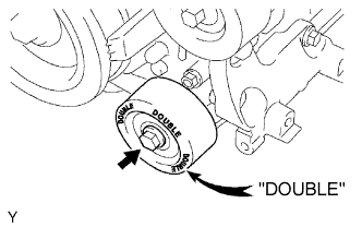
Install the idler pulley with the bolt.
- Torque:
- 54 N*m { 551 kgf*cm, 40 ft.*lbf }
Tech Tips
"DOUBLE" is marked on the No. 1 idler pulley to distinguish it from the No. 2 idler pulley.
-
-
INSTALL NO. 2 IDLER PULLEY
Note
w/o Integrated Type:
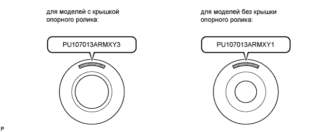
The installation of the No. 2 idler pulleys differs depending on the mark on the No. 2 idler pulleys shown in the illustration.
Tech Tips
Use the same procedure for both No. 2 idler pulleys.
-
w/ Idler Pulley Cover Plate (PU107013ARMXY3):
-
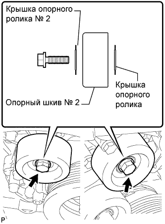
Install the idler pulley cover plate, idler pulley and No. 2 idler pulley cover plate with the bolt.
- Torque:
- 54 N*m { 551 kgf*cm, 40 ft.*lbf }
Note
-
If it is necessary to replace the pulley or either plate, replace the No. 2 idler pulley cover plate, No. 2 idler pulley and idler pulley cover plate as a set with new parts.
-
When replacing parts, make sure to replace the No. 2 idler pulley with a new pulley marked "PU107013ARMXY3".
-
-
w/o Idler Pulley Cover Plate (PU107013ARMXY1):
-
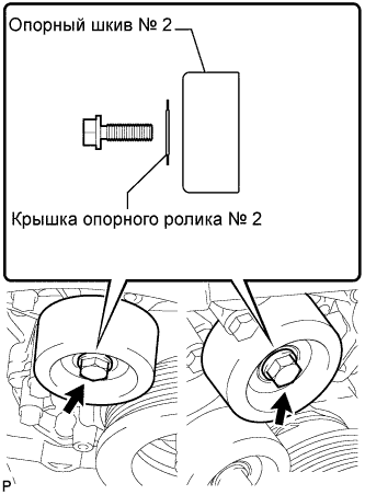
Install the idler pulley and No. 2 idler pulley cover plate with the bolt.
- Torque:
- 54 N*m { 551 kgf*cm, 40 ft.*lbf }
Note
-
If it is necessary to replace the pulley or plate, replace both the pulley and plate with a set of new parts that includes a No. 2 idler pulley cover plate, No. 2 idler pulley and idler pulley cover plate.
-
When replacing parts, make sure to replace the No. 2 idler pulley with a new pulley marked "PU107013ARMXY3".
-
-
for Integrated Type:
Install the 2 No. 2 idler pulleys with the 2 bolts.
- Torque:
- 54 N*m { 551 kgf*cm, 40 ft.*lbf }
-
-
INSTALL OIL DIPSTICK GUIDE
-
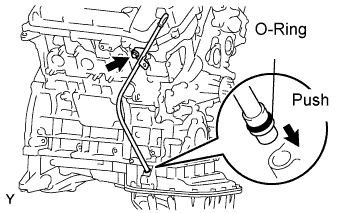
Install a new O-ring to the oil dipstick guide.
-
Apply a light coat of engine oil to the O-ring.
-
Push in the oil dipstick guide end into the guide hole of the oil pan.
-
Install the oil dipstick guide with the bolt.
- Torque:
- 9.0 N*m { 92 kgf*cm, 80 in.*lbf }
-
Install the oil dipstick gauge.
-
-
INSTALL SPARK PLUG
-
INSTALL IGNITION COIL
-
Install the 6 ignition coils with the 6 bolts.
- Torque:
- 10 N*m { 102 kgf*cm, 7 ft.*lbf }
-
-
INSTALL OIL FILLER CAP HOUSING
-
Install a new gasket and oil filler cap housing with the 2 nuts.
- Torque:
- 9.0 N*m { 92 kgf*cm, 80 in.*lbf }
-
-
INSTALL OIL FILLER CAP
-
INSTALL REAR WATER BY-PASS JOINT
-
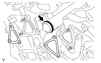
Install a new O-ring to the water outlet pipe.
-
Install 2 new gaskets and the water by-pass joint with the 2 bolts and 4 nuts.
- Torque:
- 10 N*m { 102 kgf*cm, 7 ft.*lbf, for bolts }
- 9.0 N*m { 92 kgf*cm, 80 in.*lbf, for nuts }
-
Connect the engine coolant temperature sensor connector.
-
-
INSTALL CAMSHAFT TIMING OIL CONTROL VALVE
-
Install the 2 camshaft timing oil control valves with the 2 bolts.
- Torque:
- 10 N*m { 102 kgf*cm, 7 ft.*lbf }
-
-
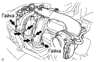
INSTALL INTAKE MANIFOLD
-
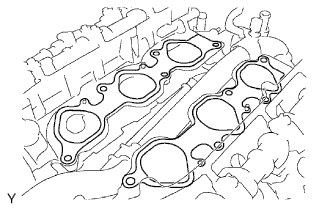
Set a new gasket on each cylinder head.
Note
-
Align the port holes of the gasket and cylinder head.
-
Be careful of the installation direction.
-
-
Set the intake manifold on the cylinder heads.
-
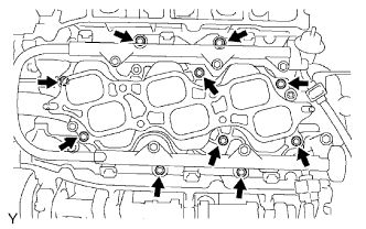
Install and uniformly tighten the 10 bolts in several passes.
- Torque:
- 26 N*m { 265 kgf*cm, 19 ft.*lbf }
-
Connect the 6 fuel injector connectors.
-
-
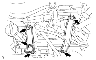
INSTALL OIL FILTER BRACKET
-
Install a new gasket and the oil filter bracket with the 3 bolts and 2 nuts.
- Torque:
- 19 N*m { 194 kgf*cm, 14 ft.*lbf }
-
-
INSTALL WATER INLET HOUSING
-
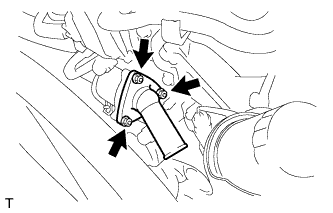
Install a new gasket to the water inlet housing with thermostat.
-
Install the water inlet housing with thermostat with the 3 nuts.
- Torque:
- 9.0 N*m { 92 kgf*cm, 80 in.*lbf }
-
-
INSTALL V-RIBBED BELT TENSIONER
-
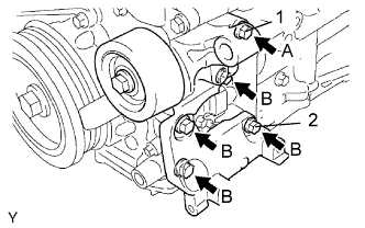
Temporarily install the V-ribbed belt tensioner with the 5 bolts.
-
Install the V-ribbed belt tensioner by tightening bolt 1 and then bolt 2.
- Torque:
- 36 N*m { 367 kgf*cm, 27 ft.*lbf }
-
Tighten the other bolts.
- Torque:
- 36 N*m { 367 kgf*cm, 27 ft.*lbf }
Tech Tips
Each bolt length is as follows:
A = 70 mm (2.76 in.)
B = 33 mm (1.30 in.)
-
-
INSTALL FRONT ENGINE MOUNTING INSULATOR LH
-
Install the engine mounting bracket with engine mounting insulator with the 3 bolts.
- Torque:
- 43 N*m { 438 kgf*cm, 32 ft.*lbf }
-
-
INSTALL FRONT ENGINE MOUNTING INSULATOR RH
-
Install the engine mounting bracket with engine mounting insulator with the 4 bolts.
- Torque:
- 43 N*m { 438 kgf*cm, 32 ft.*lbf }
-
-
INSTALL NO. 2 VENTILATION HOSE
-
INSTALL VENTILATION HOSE
-
INSTALL HEATER HOSE TO ENGINE ASSEMBLY
-
INSTALL NO. 2 RADIATOR HOSE
-
INSTALL NO. 1 RADIATOR HOSE
-
INSTALL ENGINE WIRE TO ENGINE ASSEMBLY
-
INSTALL ENGINE ASSEMBLY
-
Attach an engine sling device and chain block to the engine hangers.
-
Remove the engine from the engine stand.
-
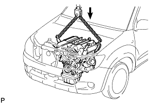
Slowly lower the engine assembly into the engine compartment.
-
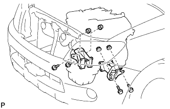
Install the engine mounting brackets to the frame with the 4 bolts and 4 nuts.
- Torque:
- 38 N*m { 387 kgf*cm, 28 ft.*lbf }
-
Remove the 4 bolts and 2 engine hangers.
-
-
INSTALL FLYWHEEL (for Manual Transmission)
-
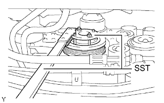
Using SST, hold the crankshaft.
- SST
- 09213-54015 ( 91651-60855 )
- 09330-00021
-
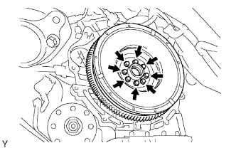
Temporarily install the flywheel with 8 new bolts.
-
Install and tighten the 8 bolts uniformly in several steps.
- Torque:
- 30 N*m { 306 kgf*cm, 22 ft.*lbf }
-
Mark the top of the bolts with paint.
-
Tighten the 8 bolts 90° in the same sequence.
-
Check that the paint marks are now at a 90° angle to the top.
-
-
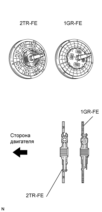
INSTALL CLUTCH DISC (for Manual Transmission)
-
Вставьте SST в ведомый диск сцепления. Затем вставьте SST (вместе с ведомым диском сцепления) в маховик.
- SST
- 09301-00110
Note
Следите за тем, чтобы ведомый диск сцепления был вставлен правильной стороной.
-
-
INSTALL CLUTCH COVER (for Manual Transmission)
-
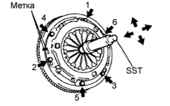
Совместите сборочные метки кожуха сцепления и маховика.
-
Затяните 6 болтов, как рассмотрено ниже.
-
Первым следует затягивать болт, который находится ближе всех к штифту.
-
Равномерно затяните 6 болтов, выбирая диаметрально противоположные пары относительно положения первого болта. Используйте для справки рисунок.
- Torque:
- 19 Н*м { 195 кгс*см, 14 фунт-сила-футов }
-
-
Слегка подвигайте SST вверх-вниз и вправо-влево.
- SST
- 09301-00110
-
Убедитесь, что диск находится по центру, а затем затяните болты.
-
-
INSTALL DRIVE PLATE AND RING GEAR ASSEMBLY (for Automatic Transmission)
-
Using SST, hold the crankshaft.
- SST
- 09213-54015 ( 91651-60855 )
- 09330-00021
-
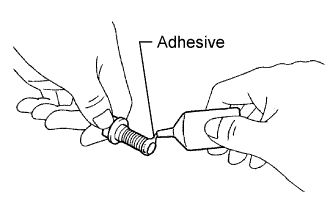
Apply adhesive to 2 or 3 threads of the mounting bolt end.
Adhesive Toyota Genuine Adhesive 1324, Three Bond 1324 or equivalent -
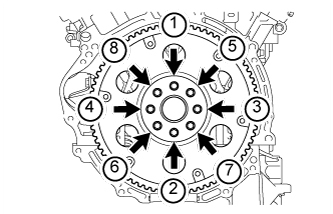
Install the front spacer, drive plate and rear spacer to the crankshaft.
-
Install and uniformly tighten the 8 bolts in several steps in the order shown in the illustration.
- Torque:
- 83 N*m { 846 kgf*cm, 61 ft.*lbf }
-
-
INSTALL MANUAL TRANSMISSION (for Manual Transmission)
-
Install the manual transmission to the vehicle Click here.
-
-
INSTALL AUTOMATIC TRANSMISSION (for Automatic Transmission)
-
Install the automatic transmission to the vehicle Click here.
-
-
INSTALL STARTER
-
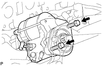
Install the starter with the 2 bolts.
- Torque:
- 58 N*m { 591 kgf*cm, 43 ft.*lbf }
-
Connect the starter wire with the nut
- Torque:
- 9.8 N*m { 100 kgf*cm, 87 in.*lbf }
-
Connect the terminal cap.
-
Connect the starter connector.
-
Connect the ground wire with the bolt
- Torque:
- 20 N*m { 202 kgf*cm, 15 ft.*lbf }
-
-
INSTALL EXHAUST MANIFOLD LH
-
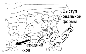
Set a new gasket to the LH cylinder head with the oval shape facing backward.
Note
Be careful of the installation direction.
-
Install the exhaust manifold with the 6 nuts. Uniformly tighten the nuts in several passes.
- Torque:
- 21 N*m { 214 kgf*cm, 15 ft.*lbf }
-
Connect the A/F sensor connector.
-
-
INSTALL EXHAUST MANIFOLD RH
-
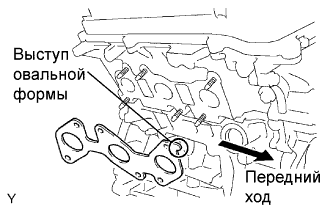
Set a new gasket to the RH cylinder head with the oval shape facing forward.
Note
Be careful of the installation direction.
-
Install the exhaust manifold with the 6 nuts. Uniformly tighten the nuts in several passes.
- Torque:
- 21 N*m { 214 kgf*cm, 15 ft.*lbf }
-
Connect the A/F sensor connector.
-
-
INSTALL FRONT FENDER APRON SEAL UPPER
-
Install the RH and LH fender apron seals with the 10 clips.
-
-
INSTALL FRONT FENDER SEAL
-
Install the RH and LH fender seals with the 10 clips.
-
Install the front tires.
-
-
INSTALL FRONT EXHAUST PIPE
-
Install the front pipe to the pipe support.
-
Install a new gasket and the front pipe to the exhaust manifold.
-
Install the front pipe with the 2 nuts.
- Torque:
- 62 N*m { 632 kgf*cm, 46 ft.*lbf }
-
-
INSTALL NO. 2 ENGINE WIRE
-
Connect the No. 2 engine wire to the cylinder block.
- Torque:
- 13 N*m { 133 kgf*cm, 10 ft.*lbf }
-
-
INSTALL ENGINE WIRE
-
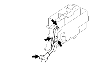
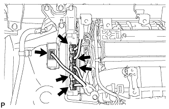
Connect the 2 engine room junction block connectors and attach the wire clamp.
-
Connect the cable to the engine room junction block with the nut.
- Torque:
- 13 N*m { 133 kgf*cm, 10 ft.*lbf }
-
Attach the 4 claws to install the side relay block cover.
-
Install the upper relay block cover.
-
Connect the ground wire with the nut.
- Torque:
- 13 N*m { 133 kgf*cm, 10 ft.*lbf }
-
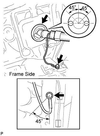
Connect the ground wire to the frame with the bolt.
- Torque:
- 13 N*m { 133 kgf*cm, 10 ft.*lbf }
-
Push the engine wire through the dash panel into the cabin.
-
Connect the A.D.D. connector.
-
Connect the ECM connectors.
-
Connect the 5 ECM connectors.
-
Connect the 4WD control ECU connector.
-
Install the glove compartment door.
-
-
Connect the wire clamp to the engine mounting bracket front LH with the bolt.
-
-
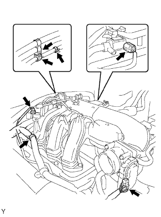
INSTALL INTAKE AIR SURGE TANK
-
Install a new gasket to the intake air surge tank.
-
Using an 8 mm hexagon socket wrench, install the intake air surge tank with the 4 bolts. Install the 2 nuts.
- Torque:
- 28 N*m { 286 kgf*cm, 21 ft.*lbf }
-
Install the 2 surge tank stays with the 4 bolts.
- Torque:
- 21 N*m { 214 kgf*cm, 15 ft.*lbf }
-
Install the oil baffle plate with the bolt.
- Torque:
- 9.0 N*m { 92 kgf*cm, 80 in.*lbf }
-
Install the throttle body bracket with the 2 bolts.
- Torque:
- 21 N*m { 214 kgf*cm, 15 ft.*lbf }
-
Install the 3 wire harness clamps and hose clamp.
-
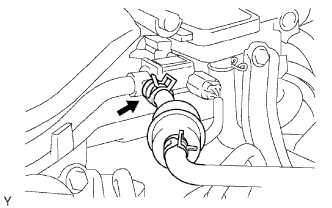
Connect the throttle position sensor and control motor connector.
-
Connect the 2 VSV connectors.
-
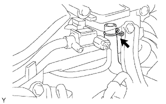
Connect the ventilation hose.
-
Connect the purge line hose.
-
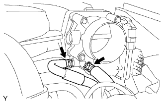
Connect the 2 water by-pass hoses.
-
-
CONNECT HEATER HOSE
-
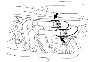
Connect the heater water inlet hose.
-
Connect the heater water outlet hose.
-
-
INSTALL NO. 2 FUEL PIPE
-
Connect the fuel pipe.
-
Check that there is no damage or contamination in the connected part of the pipe.
-
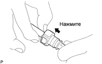
Align the axis of the connector with the axis of the pipe. Push the pipe into the connector until the connector makes a "click" sound. If the connection is tight, apply a small amount of fresh engine oil on the tip of the pipe.
-
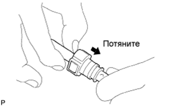
After completing the connection, try to pull apart the pipe and the connector and confirm that they are securely connected.
-
-
Install the fuel pipe clamp.
-
-
INSTALL NO. 1 FUEL PIPE
-
Connect the fuel pipe.
-
Check that there is no damage or contamination in the connected part of the pipe.
-
Align the axis of the connector with the axis of the pipe. Push the pipe into the connector until the connector makes a "click" sound. If the connection is tight, apply a small amount of fresh engine oil on the tip of the pipe.
-
After completing the connection, try to pull apart the pipe and the connector and confirm that they are securely connected.
-
-
Install the fuel pipe clamp.
-
-
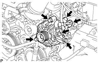
INSTALL COOLER COMPRESSOR (w/ Air Conditioning System)
-
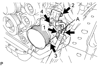
Temporarily install the compressor with the bolt labeled A.
-
Install the compressor completely by tightening the 4 bolts in the order shown in the illustration.
- Torque:
- 25 N*m { 255 kgf*cm, 18 ft.*lbf }
Note
In order to prevent misalignment, which causes belt rattle, tightening of the bolts must be performed in the order shown.
-
Connect the compressor connector.
-
Connect the suction hose with the 2 bolts.
- Torque:
- 5.4 N*m { 55 kgf*cm, 48 in.*lbf }
-
-
INSTALL IDLER PULLEY (w/o Air Conditioning System)
-
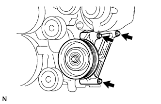
Install the idler pulley with the 3 bolts.
- Torque:
- 25 N*m { 255 kgf*cm, 18 ft.*lbf }
-
-
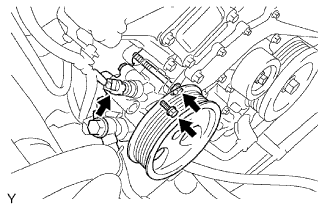
INSTALL GENERATOR
-
Install the generator and adjusting bar with the 2 bolts.
- Torque:
- 43 N*m { 438 kgf*cm, 32 ft.*lbf }
-
Install the generator wire with the nut.
- Torque:
- 9.8 N*m { 100 kgf*cm, 87 in.*lbf }
-
Install the terminal cap.
-
Connect the generator connector.
-
-
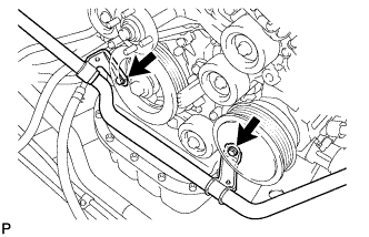
INSTALL VANE PUMP
-
Install the vane pump with the 2 bolts.
- Torque:
- 21 N*m { 214 kgf*cm, 15 ft.*lbf }
Note
Do not hit other parts with the pulley when installing the vane pump.
-
Connect the oil pressure switch connector.
-
-
INSTALL FAN PULLEY
-
INSTALL FAN WITH FLUID COUPLING
-
Temporarily install the fan with fluid coupling with the 4 nuts.
-
-
INSTALL DRIVE BELT
-
Временно установите натяжитель поликлинового ремня и закрепите его 5 болтами.
-
Установите натяжитель поликлинового ремня и закрепите его болтом 1, а затем болтом 2.
- Torque:
- 36 Н*м { 367 кгс*см, 27 фунт-сила-футов }
-
Затяните остальные болты.
- Torque:
- 36 Н*м { 367 кгс*см, 27 фунт-сила-футов }
Tech Tips
Ниже указана длина каждого болта.
A = 70 мм (2,76 дюйма)
B = 33 мм (1,30 дюйма)
-
-
TIGHTEN FAN WITH FLUID COUPLING
-
INSTALL FAN SHROUD
-
Set the fan shroud into the engine compartment.
-
Connect the 2 oil cooler hoses with the hose clamp.
-
-
INSTALL RADIATOR
-
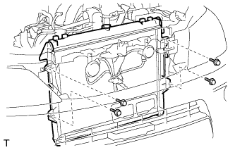
Install the radiator with the 4 bolts.
- Torque:
- 12 N*m { 122 kgf*cm, 9 ft.*lbf }
-
Attach the 4 clamps to the radiator side.
-
Connect the 2 front airbag sensor connectors.
-
-
INSTALL RADIATOR SIDE DEFLECTOR RH
-
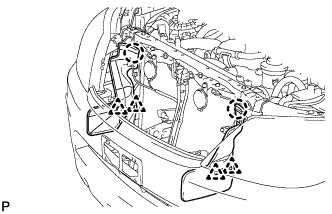
Install the deflector with the 2 clips and attach the claw.
-
-
INSTALL RADIATOR SIDE DEFLECTOR LH
-
Install the deflector with the 2 clips and attach the claw.
-
-
INSTALL AIR CLEANER
- Torque:
- 8.0 N*m { 82 kgf*cm, 71 in.*lbf }
-
INSTALL RADIATOR GRILLE
-
Установите решетку радиатора и введите в зацепление 6 захватов.
-
Установите 2 винта и 2 фиксатора.
-
-
CONNECT NO. 2 VENTILATION HOSE
-
INSTALL HOOD
-
Install the hood with the 4 bolts and adjust the hood to the correct position.
- Torque:
- 13 N*m { 133 kgf*cm, 10 ft.*lbf }
-
Connect the washer nozzle hose.
-
-
INSTALL BATTERY
-
CONNECT CABLE TO NEGATIVE BATTERY TERMINAL
-
ADD ENGINE OIL
-
Clean and install the oil drain plug with a new gasket.
- Torque:
- 40 N*m { 408 kgf*cm, 30 ft.*lbf }
-
Add fresh engine oil.
Standard capacity Item Specified Condition Drain and refill with oil filter change 5.5 liters (5.8 US qts, 4.8 Imp. qts) Drain and refill without oil filter change 5.2 liters (5.5 US qts, 4.6 Imp. qts) Dry fill 6.6 liters (7.0 US qts, 5.8 Imp. qts) Note
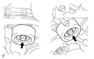
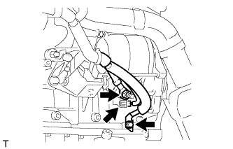
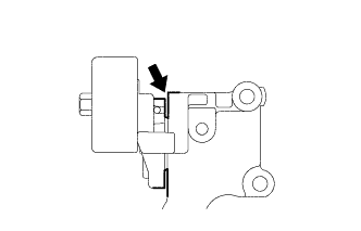
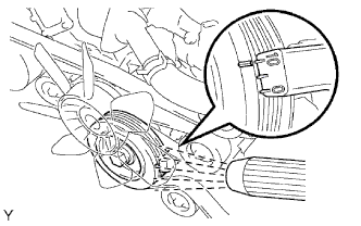
Do not allow engine oil to adhere to the moving parts of the belt tensioner, as this may cause malfunctions.
If engine oil is on the location indicated by the arrow, replace the belt tensioner.
-
Install the oil filler cap.
-
-
ADD ENGINE COOLANT
-
Tighten all the plugs and fill the radiator with TOYOTA Super Long Life Coolant (SLLC).
- Torque:
- 13 N*m { 130 kgf*cm, 9 ft.*lbf, for cylinder block drain cock plug }
Standard capacity Item Specified Condition A/T 9.8 liters (10.4 US qts, 8.6 Imp. qts) M/T 8.5 liters (9.0 US qts, 7.5 Imp. qts) Tech Tips
-
TOYOTA vehicles are filled with TOYOTA SLLC at the factory. In order to avoid damage to the engine cooling system and other technical problems, only use TOYOTA SLLC or similar high quality ethylene glycol based non-silicate, non-amine, non-nitrite, non-borate coolant with long-life hybrid organic acid technology (coolant with long-life hybrid organic acid technology consists of a combination of low phosphates and organic acids).
-
Please contact your TOYOTA dealer for further details.
Note
Never use water as a substitute for engine coolant.
-
Fill the radiator reservoir with TOYOTA Super Long Life Coolant (SLLC) to the F line.
-
Install the radiator cap.
-
Bleed air from the cooling system.
-
Warm up the engine until the thermostat opens.
While the thermostat is open, circulate the coolant for several minutes.
-
Maintain the engine speed at 2,500 to 3,000 rpm.
-
Press the inlet and outlet radiator hoses several times by hand to bleed air.
CAUTION:
When pressing the radiator hoses:
-
Wear protective gloves.
-
Be careful as the radiator hoses are hot.
-
Keep your hands away from the radiator fan.
-
-
-
Stop the engine and wait until the coolant cools down to ambient temperature.
CAUTION:
Do not remove the radiator cap while the engine and radiator are still hot. Pressurized, hot engine coolant and steam may be released and cause serious burns.
-
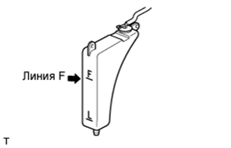
Check the coolant level in the radiator reservoir.
If the coolant level is below the L line, add SLLC to the reservoir F line.
-
-
CHECK FOR ENGINE COOLANT LEAKS
CAUTION:
Do not remove the radiator cap while the engine and radiator are still hot. Pressurized, hot engine coolant and steam may be released and cause serious burns.
-
Fill the radiator with coolant and attach a radiator cap tester.
-
Warm up the engine.
-
Using the radiator cap tester, increase the pressure inside the radiator to 118 kPa (1.2 kgf/cm2, 17.1 psi), and check that the pressure does not drop.
If the pressure drops, check the hoses, radiator and water pump for leaks. If no external leaks are found, check the cylinder block and head.
-
-
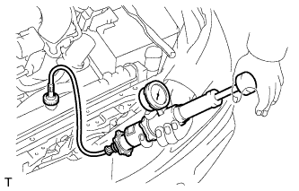
CHECK FOR FUEL LEAKS
-
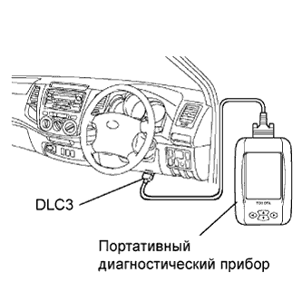
Connect the intelligent tester to the DLC3.
-
Turn the ignition switch ON.
Note
Do not start the engine.
-
Push the intelligent tester main switch ON.
-
To perform the Active Test, enter the following menus: Powertrain / Engine and ECT / Active Test / Control the Fuel Pump / Speed.
-
-
Check the fuel pump operation.
-
Check for pressure in the fuel inlet tube from the fuel line. Check that the sound of fuel flowing in the fuel tank can be heard.
If there is no sound, check the integration relay, fuel pump, ECM and wiring connector.
-
-
Check for fuel leaks.
-
Check that there are no fuel leaks after performing maintenance anywhere on the system.
If there are fuel leaks, repair or replace the leaking parts.
-
-
-
CHECK FOR ENGINE OIL LEAKS
-
Start the engine, and check that there are no oil leaks after performing maintenance.
-
-
INSTALL V-BANK COVER
-
Install the V-bank cover with the 2 nuts.
- Torque:
- 7.5 N*m { 76 kgf*cm, 66 in.*lbf }
-
-
INSPECT IGNITION TIMING
-
When using intelligent tester:
Check the ignition timing.
-
Connect the intelligent tester to the DLC3.
Tech Tips
Refer to the intelligent tester operator's manual for further details.
Standard ignition timing 7 to 24°BTDC @ idle (Transmission in neutral position) -
Disconnect the intelligent tester from the DLC3.
-
-
When not using intelligent tester:
Check the ignition timing.
-
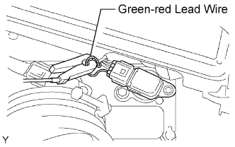
Remove the air cleaner cap.
-
Connect the tester probe of a timing light to the green-red lead wire of the ignition coil connector of the No. 1 cylinder.
-
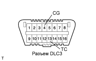
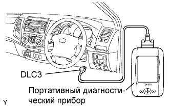
Using SST, connect terminals 13 (TC) and 4 (CG) of the DLC3.
- SST
- 09843-18040
-
Using the timing light, check the ignition timing.
Standard ignition timing 10 +-2° BTDC @ idle (Transmission in neutral position) -
Remove SST from the DLC3.
-
Check the ignition timing.
Standard ignition timing 7 to 24° BTDC @ idle (Transmission in neutral position) -
Disconnect the timing light from the engine.
-
Install the air cleaner cap.
-
-
-
INSPECT ENGINE IDLE SPEED
-
When using intelligent tester:
Check the idle speed.
-
Connect the intelligent tester to the DLC3.
Tech Tips
Refer to the intelligent tester operator's manual for further details.
-
Switch the air conditioning OFF.
-
Race the engine at 2,500 rpm for approximately 90 seconds.
-
Check the idle speed.
Standard idle speed 700 +-50 rpm (Transmission in neutral position) If the idle speed is not as specified, check the air intake system.
-
Disconnect the intelligent tester from the DLC3.
-
-
When not using intelligent tester:
Check the idle speed.
-
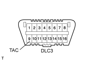
Using SST, connect the tachometer probe to terminal 9 (TAC) of the DLC3.
- SST
- 09843-18030
-
Switch the air conditioning OFF.
-
Race the engine speed at 2,500 rpm for approximately 90 seconds.
-
Check the idle speed.
Standard idle speed 700 +-50 rpm (Transmission in neutral position) If the idle speed is not as specified, check the air intake system.
-
Disconnect the tachometer from the DLC3.
-
-
-
INSPECT CO/HC
Tech Tips
This check is for determining whether or not the idle CO/HC complies with regulations.
-
Start the engine.
-
Keep the engine speed at 2,500 rpm for approximately 180 seconds.
-
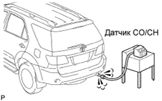
Insert a CO/HC meter testing probe at least 40 cm (1.3 ft.) into the tailpipe during idling.
-
Immediately check CO/HC concentration at idle and/or 2,500 rpm.
Tech Tips
When performing the 2 mode (2,500 rpm and idle) test, check that the CO/HC concentration complies with local regulations.
If the CO/HC concentration does not comply with regulations, troubleshoot in the order given below.
-
Check the A/F sensor operation and heated oxygen sensor operation.
-
See the table below for possible causes, then inspect and correct the applicable causes if necessary.
CO HC Symptom Causes Normal High Rough idle 1. Faulty ignitions:
-
Incorrect timing
-
Plugs are contaminated, shorted, or gaps are defective
2. Incorrect valve clearance
3. Leaky intake and exhaust valves
4. Leaky cylinder
Low High Rough idle
(Fluctuating HC reading)
1. Vacuum leaks:
-
PCV hose
-
Intake manifold
-
Throttle body
2. Lean mixture causing misfire
High High Rough idle
(Black smoke from exhaust)
1. Restricted air filter
2. Faulty SFI system:
-
Faulty pressure regulator
-
Defective ECT sensor
-
Faulty ECM
-
Faulty injector
-
Faulty throttle position sensor
-
Faulty MAF sensor
-
-
-
-
PERFORM INITIALIZATION
-
Perform initialization Click here.
Note
Certain systems need to be initialized after disconnecting and reconnecting the cable from the negative (-) battery terminal.
-