РАСПРЕДВАЛ (для ряда 2) ПРОВЕРКА
-
INSPECT CAMSHAFT
-
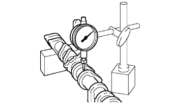
Inspect the camshaft for runout.
-
Place the camshaft on V-blocks.
-
Using a dial indicator, measure the circle runout at the center journal.
Maximum circle runout 0.06 mm (0.0024 in.) If the circle runout is greater than the maximum, replace the camshaft.
-
-
Inspect the cam lobes.
-
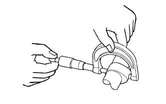
Using a micrometer, measure the cam lobe height.
Standard cam lobe height Camshaft Specified Condition Intake 44.168 to 44.268 mm (1.7389 to 1.7428 in.) Exhaust 44.580 to 44.680 mm (1.7551 to 1.7591 in.) Minimum cam lobe height Camshaft Specified Condition Intake 44.018 mm (1.7330 in.) Exhaust 44.430 mm (1.7492 in.) If the cam lobe height is less than the minimum, replace the camshaft.
-
-
Inspect the camshaft journals.
-
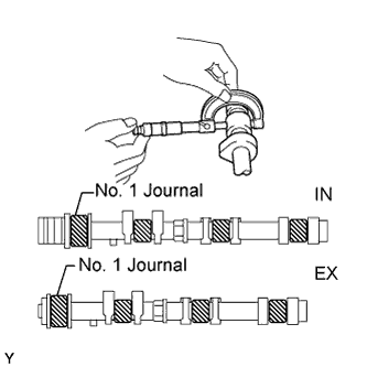
Using a micrometer, measure the journal diameter.
Standard journal diameter Journal Specified Condition No. 1 journal 35.971 to 35.985 mm (1.4162 to 1.4167 in.) Other journal 22.959 to 22.975 mm (0.9039 to 0.9045 in.) If the journal diameter is not as specified, check the oil clearance.
-
-
-
INSPECT CAMSHAFT TIMING GEAR
-
Fix the intake camshaft with a vise.
Note
Be careful not to damage the camshaft.
-
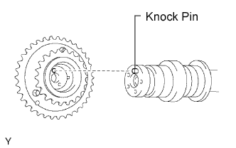
Align the knock pin hole in the camshaft timing gear with the knock pin of the camshaft, and install the camshaft timing gear with the bolt.
- Torque:
- 100 N*m { 1,020 kgf*cm, 74 ft.*lbf }
-
Confirm that the camshaft timing gear is locked.
-
Release the lock pin.
-
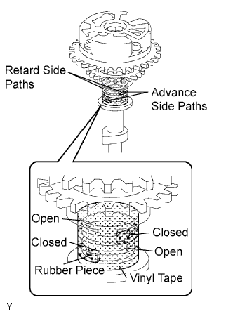
Cover the 4 oil paths of the cam journal with vinyl tape as shown in the illustration.
Tech Tips
The 4 oil paths are in the groove of the camshaft. Plug 2 of the paths with rubber pieces.
-
Break through the tape of the advance side path and the retard side path on the opposite side of the groove.
-
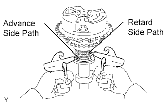
Using air guns, apply air pressure of approximately 200 kPa (2.0 kgf/cm2, 28 psi) into the 2 broken paths (advance side path and retard side path).
Note
Cover the paths with cloth or equivalent to avoid oil splashing.
-
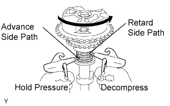
Confirm if the camshaft timing gear rotates in the timing advance direction when weakening the air pressure of the timing retard path.
Tech Tips
When the lock pin is released, the camshaft timing gear rotates in the advance direction.
-
When the camshaft timing gear comes to the most advanced position, remove the air gun from the retard side path, and then remove the air gun from the advance side path.
Note
The camshaft timing gear occasionally shifts to the retard side abruptly if the air compression of the advance side path is released before retard side path. If this abrupt shift occurs, the lock pin will break.
-
-
Check the smooth revolution.
-
Except the position where the lock pin meets at the most retarded angle, let the camshaft timing gear turn back and forth. Check the movable range and that there is no disturbance.
Standard Movable range is about 31° and gear moves smoothly. Note
Be sure to perform this check by hand, instead of air pressure.
-
-
Check the lock in the most retarded position.
-
Confirm that the camshaft timing gear is locked at the most retarded position.
-
-
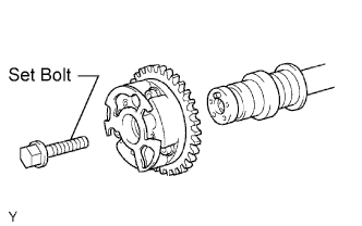
Remove the set bolt and camshaft timing gear.
Note
Be sure not to remove the other 3 bolts.
-