РАСПРЕДВАЛ (для ряда 1) СНЯТИЕ
-
DISCONNECT CABLE FROM NEGATIVE BATTERY TERMINAL
CAUTION:
Wait at least 90 seconds after disconnecting the cable from the negative (-) battery terminal to prevent airbag and seat belt pretensioner activation.
-
DISCHARGE FUEL SYSTEM PRESSURE
CAUTION:
-
Do not disconnect any part of the fuel system until you have discharged the fuel system pressure.
-
Even after discharging the fuel pressure, place a cloth or equivalent over fittings as you separate them to reduce the risk of fuel spray on yourself or in the engine compartment.
-
Disconnect the cable from the negative (-) battery terminal.
CAUTION:
Wait at least 90 seconds after disconnecting the cable from the negative (-) battery terminal to prevent airbag and seat belt pretensioner activation.
-
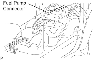
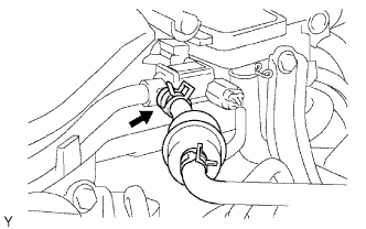
Disconnect the fuel pump connector.
-
Connect the cable to the negative (-) battery terminal.
-
Start the engine. After the engine has stopped on its own, turn the ignition switch OFF.
Tech Tips
DTC P0171/25 (system too lean) may be set.
-
Crank the engine again, and check that the engine does not start.
-
Loosen the fuel tank cap, then discharge the pressure in the fuel tank completely.
-
Connect the fuel pump connector.
-
-
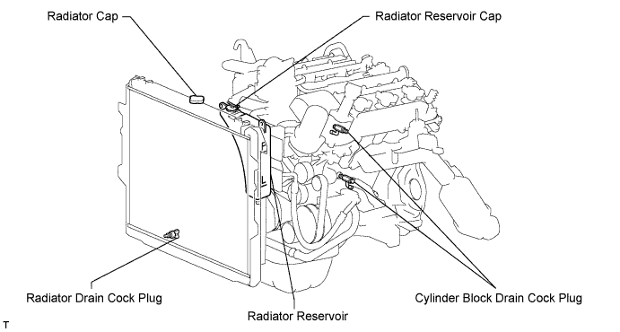
DRAIN ENGINE COOLANT
-
Remove the radiator cap.
-
Loosen the 2 cylinder block drain cock plugs and radiator drain cock plug, and then drain the coolant.
Tech Tips
Collect the coolant in a container and dispose of it according to the regulations in your area.
-
-
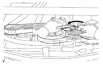
REMOVE DRIVE BELT
-
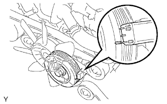
Ослабьте натяжение ремня, повернув натяжитель ремня против часовой стрелки, и снимите поликлиновой ремень с натяжителя.
-
-
REMOVE V-BANK COVER
-
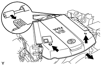
Remove the 2 nuts and V-bank cover.
-
-
REMOVE NO. 2 VENTILATION HOSE
-
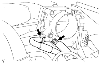
REMOVE AIR CLEANER
-
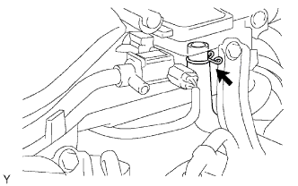
Disconnect the vacuum hose.
-
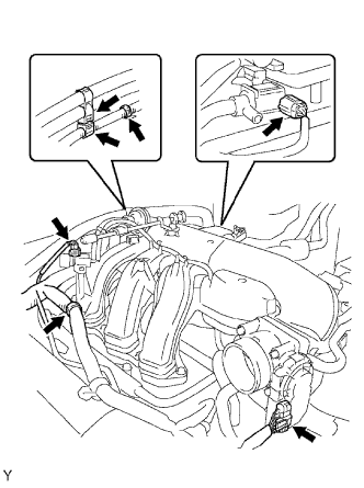
Disconnect the MAF meter connector.
-
Remove the 2 wire harness clamps.
-
Loosen the 2 hose clamps.
-
Remove the 2 bolts and air cleaner.
-
-
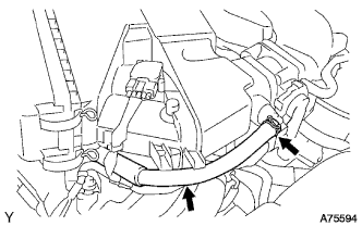
REMOVE INTAKE AIR SURGE TANK
-
Disconnect the 2 water by-pass hose.
-
Disconnect the purge line hose.
-
Disconnect the ventilation hose.
-
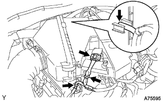
Disconnect the 2 VSV connectors.
-
Disconnect the throttle body with motor connector.
-
Separate the 3 wire harness clamps and hose clamp.
-
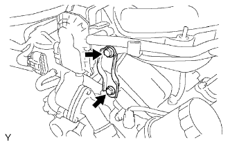
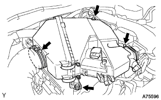
Remove the 2 bolts and throttle body bracket.
-
Remove the bolt and oil baffle plate.
-
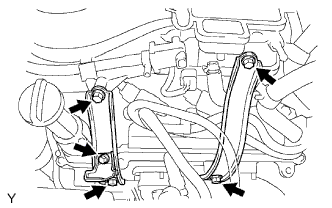
Remove the 4 bolts and 2 surge tank stays.
-
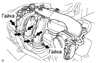
Remove the 2 nuts.
-
Using an 8 mm socket hexagon wrench, remove the 4 bolts, intake air surge tank and gasket.
-
-
REMOVE IGNITION COIL
-
REMOVE CYLINDER HEAD COVER RH
-
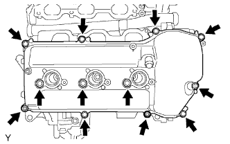
Remove the 10 bolts, 3 seal washers, 2 nuts, cylinder head cover and gasket.
-
-
REMOVE CYLINDER HEAD COVER LH
-
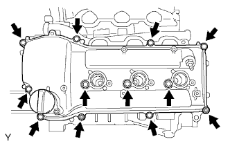
Remove the 10 bolts, 3 seal washers, 2 nuts, cylinder head cover and gasket.
-
-
SET NO. 1 CYLINDER TO TDC/COMPRESSION
-
Turn the crankshaft pulley, and align the notch with timing mark 0 of the timing chain cover.
-
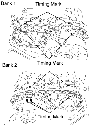
Check that the timing marks of the camshaft timing gears are aligned with the timing marks of the bearing cap as shown in the illustration.
If the timing marks are not aligned, turn the crankshaft 1 complete revolution (360°) and align the timing marks as described above.
-

Place paint marks on the No. 1 chain links that correspond with the timing marks of the camshaft timing gears.
-
-
REMOVE NO. 1 CHAIN TENSIONER
Note
-
Never rotate the crankshaft with the chain tensioner removed.
-
When rotating the camshaft with the timing chain removed, rotate the crankshaft counterclockwise 40° from the TDC first.
-
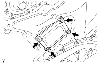
Remove the 4 bolts, timing chain cover plate and gasket.
-
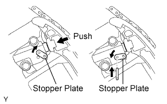
While turning the stopper plate of the tensioner clockwise, push in the plunger of the chain tensioner as shown in the illustration.
-
While turning the stopper plate of the tensioner counterclockwise, insert a pin of φ3.5 mm (0.138 in.) into the holes on the stopper plate and tensioner to fix the stopper plate.
-
Remove the 2 bolts and chain tensioner.
-
-
REMOVE NO. 2 CAMSHAFT
Note
As the thrust clearance of the camshaft is small, the camshaft must be kept level while it is being removed. If the camshaft is not kept level, the portion of the cylinder head which receives the shaft thrust may crack or be damaged, causing the camshaft to seize or break. To avoid this, the following steps should be carried out.
-
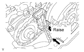
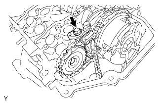
While raising up the No. 2 chain tensioner, insert a pin of φ1.0 mm (0.039 in.) into the hole to fix it.
-
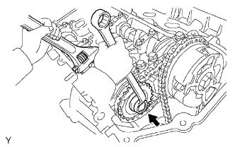
Hold the hexagonal portion of the No. 2 camshaft with a wrench, and remove the camshaft timing gear set bolt.
Note
Be careful not to damage the cylinder head and valve lifter with the wrench.
-
Separate the camshaft timing gear from the No. 2 camshaft.
-
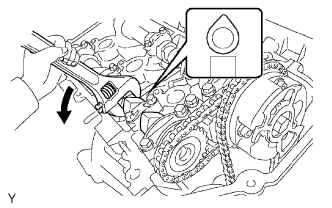
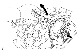
Rotate the camshaft counterclockwise using the wrench so that the cam lobes of the No. 1 cylinder face upward as shown in the illustration.
-
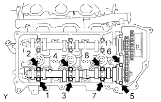
Uniformly loosen and remove the 8 bearing cap bolts in several passes in the sequence shown in the illustration.
-
Remove the 4 bearing caps and No. 2 camshaft.
-
-
REMOVE NO. 2 CHAIN TENSIONER
-
Remove the No. 2 chain tensioner bolt, and then remove the No. 2 chain tensioner and camshaft timing gear.
-
-
REMOVE NO. 1 CAMSHAFT
Note
As the thrust clearance of the camshaft is small, the camshaft must be kept level while it is being removed. If the camshaft is not kept level, the portion of the cylinder head which receives the shaft thrust may crack or be damaged, causing the camshaft to seize or break. To avoid this, the following steps should be carried out.
-
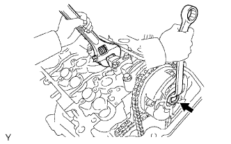
Hold the hexagonal portion of the No. 1 camshaft with a wrench, and loosen the camshaft timing gear set bolt.
Note
-
Be careful not to damage the cylinder head and valve lifter with the wrench.
-
Do not disassemble the camshaft timing gear assembly.
-
-
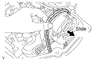
Slide the camshaft timing gear and separate the No. 1 chain from the camshaft timing gear.
-
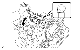
Rotate the No. 1 camshaft counterclockwise using the wrench so that the cam lobes of the No. 1 cylinder face downward as shown in the illustration.
-
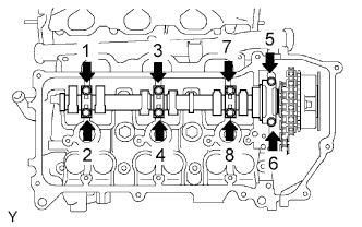
Loosen and remove the 8 bearing cap bolts in several passes in the sequence shown in the illustration.
-
Remove the 4 bearing caps.
-
Remove the camshaft timing gear set bolt with the No. 1 camshaft lifted up, and then remove the No. 1 camshaft and camshaft timing gear with No. 2 chain.
-
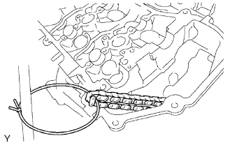
Tie the No. 1 chain with a string as shown in the illustration.
Note
Be careful not to drop anything inside the timing chain cover.
-