БЛОК ДВИГАТЕЛЯ ПОВТОРНАЯ СБОРКА

-
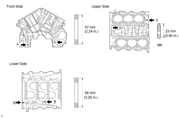
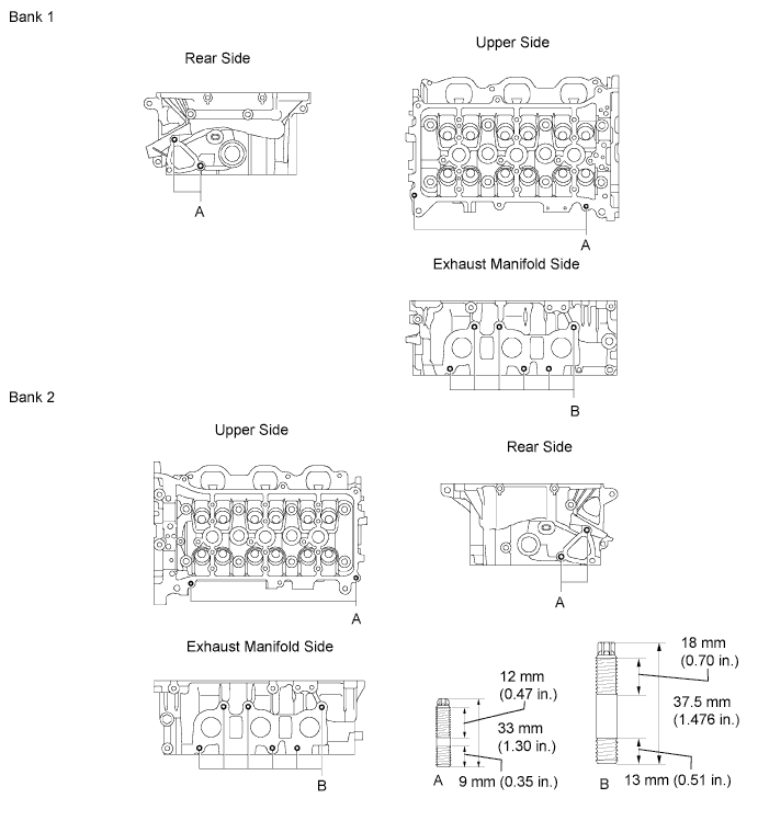
INSTALL STUD BOLT (for Cylinder Block)
-
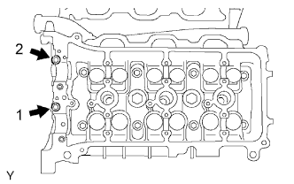
Install the stud bolts as shown in the illustration.
- Torque:
- 11 N*m { 112 kgf*cm, 8.1 ft.*lbf, for stud bolt A }
- 4.5 N*m { 46 kgf*cm, 40 in.*lbf, for stud bolt B }
- 4.0 N*m { 41 kgf*cm, 35 in.*lbf, for stud bolt C }
-
-
INSTALL STRAIGHT PIN (for Cylinder Block)
-
Using a plastic-faced hammer, tap in new straight pins to the specified protrusion height.
Standard protrusion Pin A 22.5 to 23.5 mm (0.886 to 0.925 in.) Pin B 10.5 to 11.5 mm (0.413 to 0.453 in.) Pin C 8.5 to 9.5 mm (0.335 to 0.374 in.) Pin D 5.5 to 6.5 mm (0.217 to 0.256 in.) 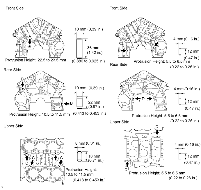
-
-
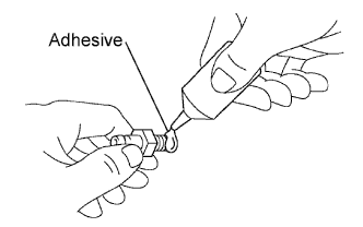
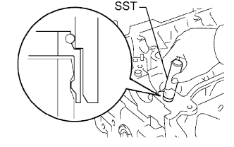
INSTALL TIGHT PLUG (for Cylinder Block)
-
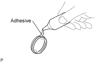
Apply adhesive around the tight plugs.
Adhesive Toyota Genuine Adhesive 1324, Three Bond 1324 or equivalent -
Using SST, tap in the tight plugs to the specified depth as shown in the illustration.
- SST
- 09950-60010 ( 09951-00350 )
- 09950-70010 ( 09951-07150 )
Standard depth 0.2 to 1.2 mm (0.008 to 0.047 in.) 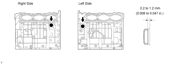
-
-
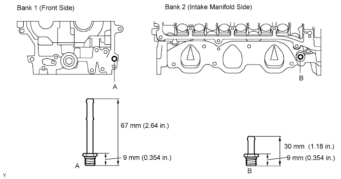
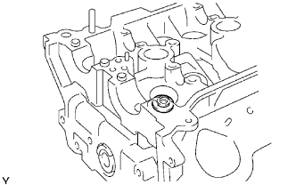
INSTALL OIL JET
-
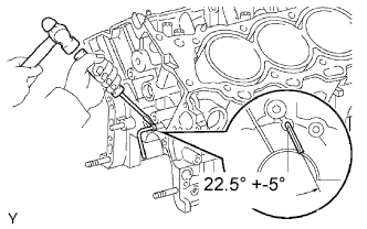
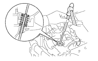
Using a screwdriver and hammer, tap in the oil jet.
-
-
INSTALL OIL NOZZLE
-
Using a 5 mm socket hexagon wrench, install the 3 oil nozzles.
- Torque:
- 9.0 N*m { 92 kgf*cm, 80 in.*lbf }
-
-
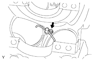
INSTALL PISTON PIN HOLE SNAP RING
-
Using a small screwdriver, install a new snap ring at one end of the piston pin hole.
Note
Be sure that the end gap of the snap ring is not aligned with the pin hole cutout portion of the piston.
-
-
INSTALL PISTON
-
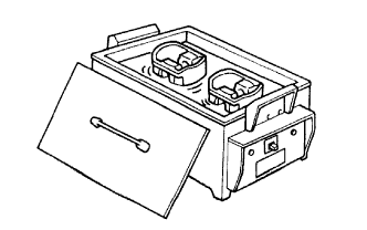
Gradually heat the piston to about 80 to 90°C (176 to 194°F).
-
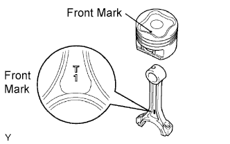
Coat the piston pin with engine oil.
-
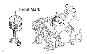
Align the front marks of the piston and connecting rod, and push in the piston pin with your thumb.
-
-
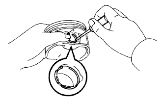
INSTALL PISTON PIN HOLE SNAP RING
-
Using a small screwdriver, install a new snap ring on the other end of the piston pin hole.
Note
Be sure that the end gap of the snap ring is not aligned with the pin hole cutout portion of the piston.
-
-
INSTALL PISTON RING SET
-
Install the oil ring expander and 2 side rails by hand.
-
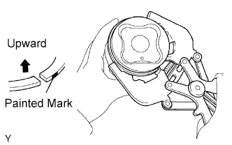
Using a piston ring expander, install the 2 compression rings.
Note
Install the No. 2 compression ring with the painted mark facing the right side.
-
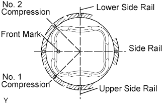
Position the piston rings so that the ring ends are as shown.
-
-
INSTALL CONNECTING ROD BEARING
-
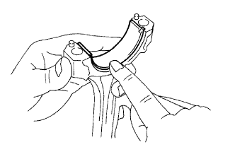
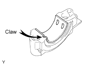
Align the bearing claw with the groove of the connecting rod or connecting cap.
Note
Clean the backside of the bearing and the bearing surface of the connecting rod. Keep the surfaces free from oils and fats.
-
-
INSTALL CRANKSHAFT BEARING
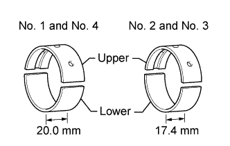
Tech Tips
Main bearings come in widths of 17.4 mm (0.685 in.) and 20.0 mm (0.787 in.). Install the 20.0 mm (0.787 in.) bearings in the No. 1 and No. 4 cylinder block journal positions with the main bearing cap. Install the 17.4 mm (0.685 in.) bearings in the No. 2 and No. 3 positions.
-
Clean each main journal and bearing.
-
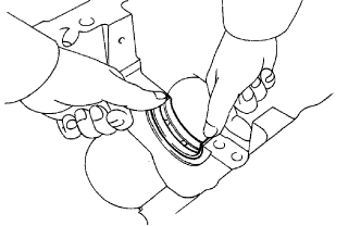
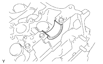
Align the bearing claw with the claw groove of the cylinder block, and push in the 4 upper bearings.
Note
Do not apply engine oil to the bearing and its contact surface.
-
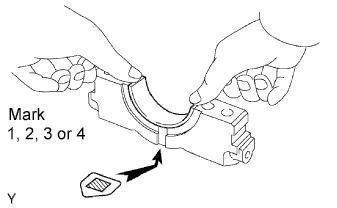
Align the bearing claw with the claw groove of the main bearing cap, and push in the 4 lower bearings.
Note
Do not apply engine oil to the bearing and its contact surface.
Tech Tips
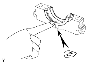
A number is marked on each main bearing cap to indicate the installation position.
-
-
INSTALL CRANKSHAFT
-
Apply engine oil to the upper bearing and install the crankshaft on the cylinder block.
-
Install the 2 upper thrust washers to the No. 2 journal position of the cylinder block.
-
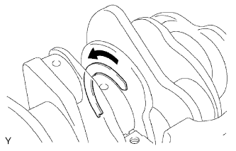
Push the crankshaft toward the front (rear) side.
-
Install the 2 upper thrust washers with the oil grooves facing outward.
-
-
Install the 2 lower thrust washers on the No. 2 bearing cap with the grooves facing outward.
-
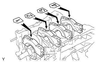
Examine the front marks and numbers, and install the bearing caps on the cylinder block.
-
Apply a light coat of engine oil on the threads and under the heads of the bearing cap bolts.
-
Temporarily install the 8 main bearing cap bolts to the inside positions.
-
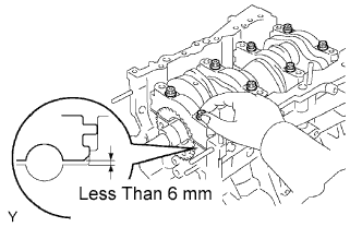
Insert the main bearing cap by hand until the clearance between the main bearing cap and the cylinder block is less than 6 mm (0.23 in.) by using the 2 internal bearing cap bolts as a guide.
-
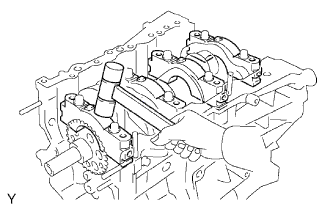
Using a plastic-faced hammer, lightly tap the bearing cap to ensure a proper fit.
-
Apply a light coat of engine oil on the threads and under the heads of the main bearing cap bolts.
-
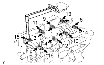
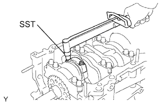
Install and uniformly tighten the 16 main bearing cap bolts in several passes, in the sequence shown.
- Torque:
- 61 N*m { 622 kgf*cm, 45 ft.*lbf }
-
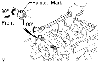
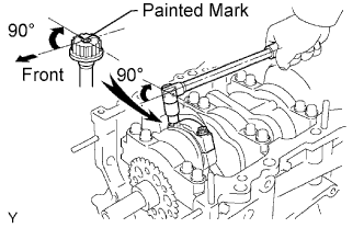
Mark the front side of the bearing cap bolts with paint.
-
Retighten the bearing cap bolts by 90° in the sequence shown.
-
Check that the painted mark is now at a 90°angle to the front.
-
Check that the crankshaft turns smoothly.
-
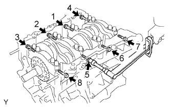
Install and uniformly tighten the 8 main bearing cap bolts in several passes, in the sequence shown.
- Torque:
- 35 N*m { 357 kgf*cm, 26 ft.*lbf }
-
-
CHECK CRANKSHAFT THRUST CLEARANCE
-
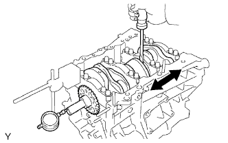
Using a dial indicator, measure the thrust clearance while prying the crankshaft back and forth with a screwdriver.
Standard thrust clearance 0.04 to 0.24 mm (0.0016 to 0.0094 in.) Maximum thrust clearance 0.30 mm (0.0118 in.) If the thrust clearance is greater than the maximum, replace the thrust washers as a set or a crankshaft.
Tech Tips
Thrust washer thickness: 1.93 to 1.98 mm (0.0760 to 0.0780 in.)
-
-
INSTALL PISTON WITH CONNECTING ROD
-
Apply engine oil to the cylinder walls, the pistons, and the surfaces of connecting rod bearings.
-
Check the position of the piston ring ends.
-
Using a piston ring compressor, push the correctly numbered piston and connecting rod assemblies into each cylinder with the front mark of the piston facing forward.
Note
-
Clean the backside of the bearing and the bearing surface of the connecting rod cap. Keep the surfaces free from oils and fats.
-
Match the numbered connecting rod cap.
-
-
Check that the protrusion of the connecting rod cap is facing in the correct direction.
-
Apply a light coat of engine oil on the threads and under the heads of the connecting rod cap bolts.
-
Using SST, tighten the bolts in several passes to the specified torque.
- SST
- 09011-38121
- Torque:
- 25 N*m { 250 kgf*cm, 18 ft.*lbf }
-
Mark the front side of each connecting cap bolt with paint.
-
Retighten the cap bolts by 90° as shown.
-
Check that the crankshaft turns smoothly.
-
-
CHECK CONNECTING ROD THRUST CLEARANCE
-
Using a dial indicator, measure the thrust clearance while moving the connecting rod back and forth.
Standard thrust clearance 0.15 to 0.30 mm (0.0059 to 0.0118 in.) Maximum thrust clearance 0.35 mm (0.0138 in.) If the thrust clearance is greater than the maximum, replace the connecting rod assembly. If necessary, replace the crankshaft.
-
-
INSTALL RING PIN (for Cylinder Head)
-
Using a plastic-faced hammer, tap in new ring pins to the specified protrusion height.
Standard protrusion height 2.7 to 3.3 mm (0.106 to 0.130 in.) 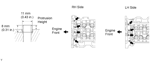
-
-
INSTALL STRAIGHT PIN (for Cylinder Head)
-
Using a plastic-faced hammer, tap in new straight pins to the specified protrusion height.
Standard protrusion height Item Specified Condition A 17.5 to 19.5 mm (0.689 to 0.768 in.) B 7.5 to 8.5 mm (0.295 to 0.335 in.) C 7.0 to 9.0 mm (0.276 to 0.354 in.) 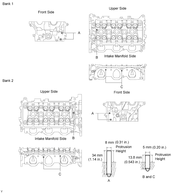
-
-
INSTALL STUD BOLT (for Cylinder Head)
-
Using E5 and E7 "torx" socket wrenches, install the stud bolts.
- Torque:
- 4.0 N*m { 41 kgf*cm, 35 in.*lbf, for stud bolt A }
- 9.0 N*m { 92 kgf*cm, 80 in.*lbf, for stud bolt B }
-
-
INSTALL UNION (for Cylinder Head)
-
Apply adhesive to 2 or 3 threads of the bolt end.
Adhesive Toyota Genuine Adhesive 1324, Three Bond 1324 or equivalent -
Using a 12 mm deep socket wrench, install the unions.
- Torque:
- 15 N*m { 150 kgf*cm, 11 ft.*lbf }
-
-
INSTALL TIGHT PLUG (for Cylinder Head)
-
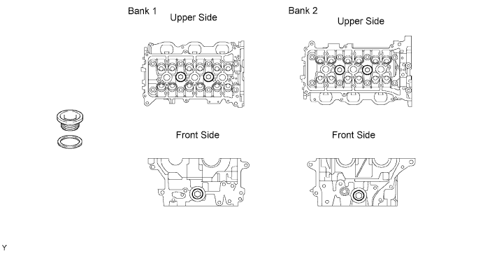
Apply adhesive around the tight plugs as shown in the illustration.
Adhesive Toyota Genuine Adhesive 1324, Three Bond 1324 or equivalent -
Using SST, tap in the tight plugs to the specified depth.
- SST
- 09950-60010 ( 09951-00250 )
- 09950-70010 ( 09951-07150 )
Standard depth 1.5 mm (0.059 in.) 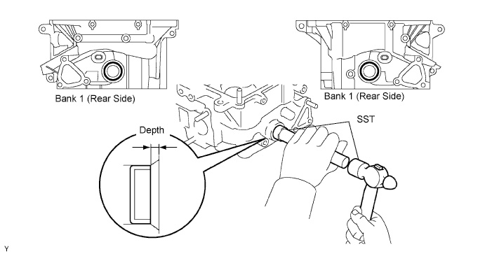
-
-
INSTALL STRAIGHT SCREW PLUG (for Cylinder Head)
-
Using a 16 mm hexagon wrench, install a new gasket and the straight screw plug.
- Torque:
- 80 N*m { 816 kgf*cm, 59 ft.*lbf }
-
-
INSTALL VALVE STEM OIL SEAL
-
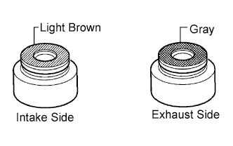
Apply a light coat of engine oil to the valve guide bush.
Tech Tips
The intake valve stem oil seal is light brown and the exhaust valve stem oil seal is gray.
-
Using SST, push in a new valve stem oil seal.
- SST
- 09201-41020
-
-
INSTALL VALVE SPRING SEAT
-
INSTALL VALVE
-
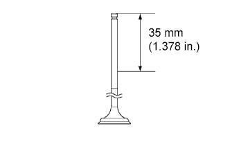
Apply engine oil to the valve as shown in the illustration.
-
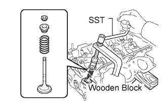
Place the cylinder head on a wooden block.
-
Install the valve, inner compression spring and valve spring retainer.
-
Using SST, compress the inner compression spring and place the 2 valve spring retainer locks around the valve stem.
- SST
- 09202-70020 ( 09202-00010 )
-
Using a 5 mm pin punch, lightly tap the valve stem tip to ensure a proper fit.
Note
Be careful not to damage the valve stem tip.
-
-
INSTALL VALVE LIFTER
-
Apply engine oil to the valve stem end and valve lifter, and install the valve lifter.
-
Check that the valve lifter rotates smoothly by hand.
-
-
INSTALL ENGINE REAR OIL SEAL RETAINER
-
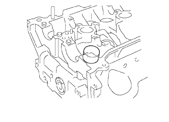
Remove any old packing (FIPG) material and be careful not to drop any oil on the contact surfaces of the oil seal retainer and cylinder block.
-
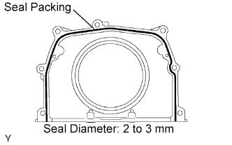
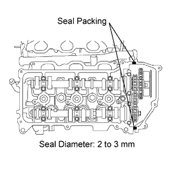
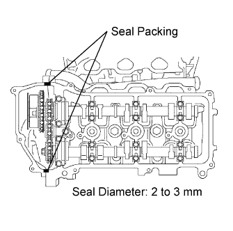
Apply a continuous line of seal packing to the oil seal retainer as shown in the illustration.
Seal packing Toyota Genuine Seal Packing Black, Three Bond 1207B or equivalent Standard seal diameter 2 to 3 mm (0.08 to 0.12 in.) Note
Parts must be assembled within 3 minutes of application. Otherwise the seal packing must be removed and reapplied.
-
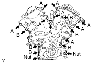
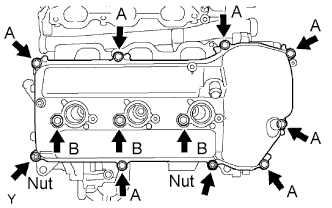
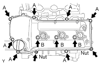
Install the oil seal retainer with the 5 bolts and 2 nuts.
- Torque:
- 9.0 N*m { 92 kgf*cm, 80 in.*lbf }
-
-
INSTALL KNOCK SENSOR
-
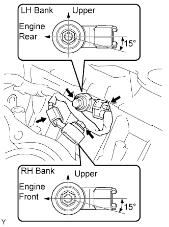
Install the 2 knock sensors with the 2 bolts as shown in the illustration.
- Torque:
- 20 N*m { 204 kgf*cm, 15 ft.*lbf }
-
Connect the knock sensor connectors.
-
-
INSTALL NO. 1 WATER OUTLET PIPE
-
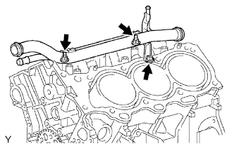
Install the water outlet pipe with the bolt and 2 nuts.
- Torque:
- 10 N*m { 102 kgf*cm, 7 ft.*lbf }
-
-
INSTALL CYLINDER HEAD GASKET
-
Remove any old packing (FIPG) material and be careful not to drop any oil on the contact surfaces of the cylinder head and cylinder block.
-
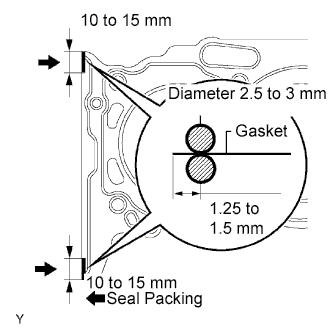
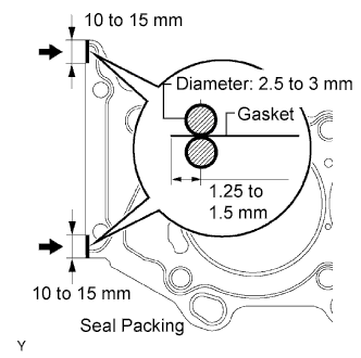
Apply seal packing to a new cylinder head gasket as shown in the illustration.
Seal packing Toyota Genuine Seal Packing Black, Three Bond 1207B or equivalent Standard seal diameter 2.5 to 3 mm (0.098 to 0.118 in.) Note
Install the cylinder head within 3 minutes after applying seal packing. After installing it, cylinder head bolts must be tightened within 15 minutes. Otherwise the seal packing must be removed and reapplied.
-
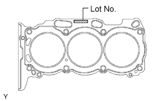
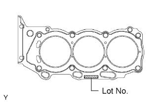
Place the cylinder head gasket on the cylinder block surface with the Lot No. stamp facing upward.
Note
-
Be careful of the installation direction.
-
Place the cylinder head carefully in order not to damage the gasket with the bottom part of the head.
-
-
-
INSTALL CYLINDER HEAD
-
Place the bank 1 cylinder head on the cylinder head gasket.
-
Install the 8 cylinder head bolts.
Tech Tips
-
The cylinder head bolts are tightened in 2 progressive steps.
-
If any cylinder head bolt is broken or deformed, replace it.
-
Apply a light coat of engine oil on the threads and under the heads of the cylinder head bolts.
-
Install the plate washer to the cylinder head bolt.
-
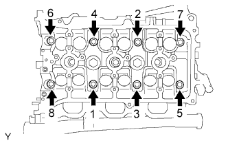
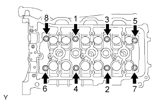
Using a 10 mm bi-hexagon wrench, temporarily tighten each bolt in several passes in the sequence shown in the illustration. Then tighten to the specified torque.
- Torque:
- 36 N*m { 367 kgf*cm, 27 ft.*lbf }
If any one of the cylinder head bolts does not meet the torque specification, replace the cylinder head bolt.
Note
Do not drop the washers into the cylinder head.
-
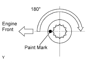
Mark the front side of each cylinder head bolt with paint.
-
Retighten the cylinder head bolts by 180° in the numerical order shown.
-
Check that the painted marks are now at a 180° angle to the front.
-
-
-
INSTALL NO. 2 CYLINDER HEAD GASKET
-
Remove any old packing (FIPG) material and be careful not to drop any oil on the contact surfaces of the cylinder head and cylinder block.
-
Apply seal packing to a new cylinder head gasket as shown in the illustration.
Seal packing Toyota Genuine Seal Packing Black, Three Bond 1207B or equivalent Standard seal diameter 2.5 to 3 mm (0.098 to 0.118 in.) Note
Install the cylinder head within 3 minutes after applying seal packing. After installing it, cylinder head bolts must be tightened within 15 minutes. Otherwise the seal packing must be removed and reapplied.
-
Place the cylinder head gasket on the cylinder block surface with the Lot No. stamp facing upward.
Note
-
Be careful of the installation direction.
-
Place the cylinder head carefully in order not to damage the gasket with the bottom part of the head.
-
-
-
INSTALL CYLINDER HEAD LH
-
Place the bank 2 cylinder head on the cylinder head gasket.
-
Install the 8 cylinder head bolts.
Tech Tips
-
The cylinder head bolts are tightened in 2 progressive steps.
-
If any cylinder head bolt is broken or deformed, replace it.
-
Apply a light coat of engine oil on the threads and under the heads of the cylinder head bolts.
-
Install the plate washer to the cylinder head bolt.
-
Using a 10 mm bi-hexagon wrench, temporarily tighten each bolt in several passes in the sequence shown in the illustration. Then tighten to the specified torque.
- Torque:
- 36 N*m { 367 kgf*cm, 27 ft.*lbf }
If any one of the cylinder head bolts does not meet the torque specification, replace the cylinder head bolt.
Note
Do not drop the washers into the cylinder head.
-
Mark the front side of each cylinder head bolt with paint.
-
Retighten the cylinder head bolts by 180°in the numerical order shown.
-
Check that the painted marks are now at a 180° angle to the front.
-
-
Install the 2 cylinder head bolts.
-
Apply a light coat of engine oil on the threads and under the heads of the cylinder head bolts.
-
Install and uniformly tighten the 2 cylinder head bolts in several passes, in the sequence shown.
- Torque:
- 30 N*m { 306 kgf*cm, 22 ft.*lbf }
-
-
-
INSTALL NO. 1 CAMSHAFT BEARING
-
Align the bearing claw with the claw groove of the bearing cap, and push in the camshaft bearing.
Note
-
Install the bearing while aligning with the oil hole in the bearing cap.
-
Clean the backside of the bearing and the bearing surface of the bearing cap. Keep the surfaces free from oils and fats.
-
-
-
INSTALL NO. 2 CAMSHAFT BEARING
-
Install the No. 2 camshaft bearing to the cylinder head.
Note
Clean the backside of the bearing and the bearing surface of the cylinder head. Keep the surfaces free from oils and fats.
-
-
INSTALL CAMSHAFT
Note
As the thrust clearance of the camshaft is small, the camshaft must be kept level while it is being installed. If the camshaft is not kept level, the portion of the cylinder head which receives the shaft thrust may crack or be damaged, causing the camshaft to seize or break. To avoid this, the following steps should be carried out.
-
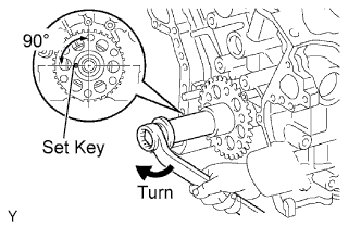
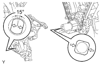
Set the crankshaft position.
-
Using the crankshaft pulley set bolt, turn the crankshaft, and set the crankshaft set key into the left horizontal position.
Note
Having the crankshaft at the wrong angle can cause the piston head and valve head to come into contact with each other when installing the camshaft, causing damage. Always set the crankshaft at the correct angle.
-
-
Apply new engine oil to the thrust portion and journal of the camshafts.
-
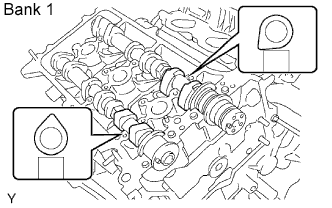
Install the camshaft of the bank 1.
-
Place the 2 camshafts onto the bank 1 cylinder head with the cam lobes of the No. 1 cylinder as shown in the illustration.
-
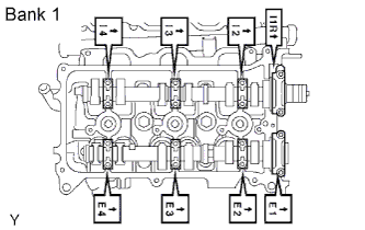
Install the 8 bearing caps in their proper locations.
-
Apply a light coat of engine oil on the threads and under the heads of the bearing cap bolts.
-
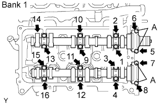
Install and uniformly tighten the 16 bearing cap bolts in several passes, in the sequence shown.
- Torque:
- 9.0 N*m { 92 kgf*cm, 80 in.*lbf, for 10 mm (0.39 in.) head }
- 24 N*m { 245 kgf*cm, 18 ft.*lbf, for 12 mm (0.47 in.) head (A) }
-
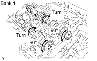
Rotate the camshafts clockwise using the hexagonal portion of each camshaft. Rotate the camshafts so that the camshaft knock pin on the cylinder head rotates by 90°.
-
-
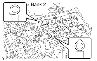
Install the camshafts of the bank 2.
-
Place the 2 camshafts onto the bank 2 cylinder head with the cam lobes of the No. 2 cylinder as shown in the illustration.
-
Install the 8 bearing caps in their proper locations.
-
Apply a light coat of engine oil on the threads and under the heads of the bearing cap bolts.
-
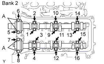
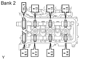
Install and uniformly tighten the 16 bearing cap bolts in several passes, in the sequence shown.
- Torque:
- 9.0 N*m { 92 kgf*cm, 80 in.*lbf, for 10 mm (0.39 in.) head }
- 24 N*m { 245 kgf*cm, 18 ft.*lbf, for 12 mm (0.47 in.) head (A) }
-
-
-
INSTALL NO. 2 CHAIN TENSIONER
-
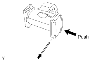
While pushing in the tensioner, insert a pin of φ1.0 mm (0.039 in.) into the hole to fix it.
-
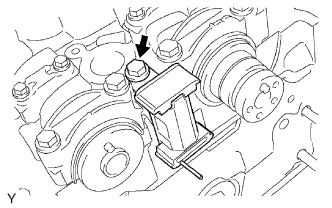
Install the No. 2 chain tensioner with the bolt.
- Torque:
- 19 N*m { 194 kgf*cm, 14 ft.*lbf }
-
-
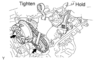
INSTALL CAMSHAFT TIMING GEARS AND NO. 2 CHAIN (for Bank 1)
-
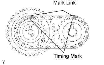
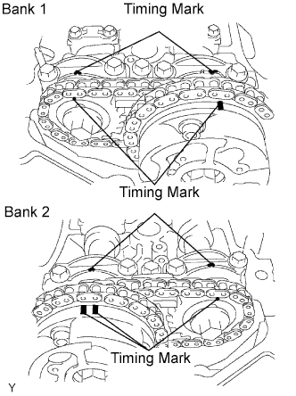
Align the mark links (yellow) with the timing marks (1 dot mark) of the camshaft timing gears as shown in the illustration.
-
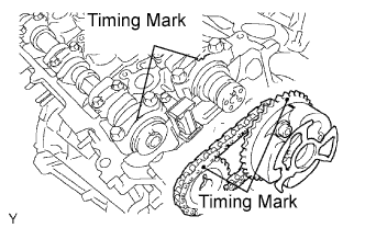
Align the timing marks on the camshaft timing gears with the timing marks on the bearing caps, and install the camshaft timing gears with the chain to the RH camshafts.
-
Temporarily install the 2 camshaft timing gear bolts.
Note
Do not push the camshaft timing gear assembly toward the camshaft forcibly when installing it.
-
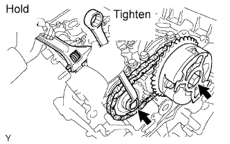
Hold the hexagonal portion of the camshaft with a wrench, and tighten the 2 bolts.
- Torque:
- 100 N*m { 1,020 kgf*cm, 74 ft.*lbf }
-
Remove the pin from the No. 2 chain tensioner.
-
-
INSTALL NO. 3 CHAIN TENSIONER
-
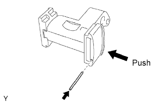
While pushing in the tensioner, insert a pin of φ1.0 mm (0.039 in.) into the hole to hold it.
-
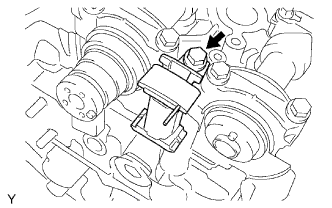
Install the No. 3 chain tensioner with the bolt.
- Torque:
- 19 N*m { 194 kgf*cm, 14 ft.*lbf }
-
-
INSTALL CAMSHAFT TIMING GEARS AND NO. 2 CHAIN (for Bank 1)
-
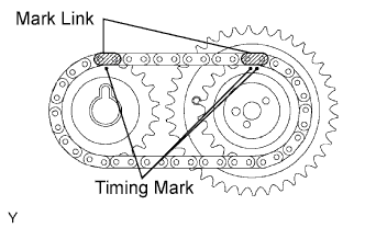
Align the mark links (yellow) with the timing marks (1 dot mark and 2 dot mark) of the camshaft timing gears as shown in the illustration.
-
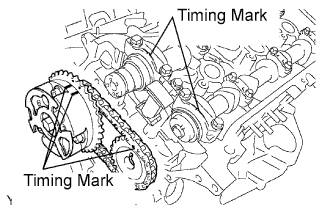
Align the timing marks on the camshaft timing gears with the timing marks on the bearing caps, and install the camshaft timing gears with the chain to the LH camshafts.
-
Temporarily install the 2 camshaft timing gear bolts.
Note
Do not push the camshaft timing gear assembly toward the camshaft forcibly when installing it.
-
Hold the hexagonal portion of the camshaft with a wrench, and tighten the 2 bolts.
- Torque:
- 100 N*m { 1,020 kgf*cm, 74 ft.*lbf }
-
Remove the pin from the No. 3 chain tensioner.
-
-
INSTALL NO. 1 CHAIN VIBRATION DAMPER
-
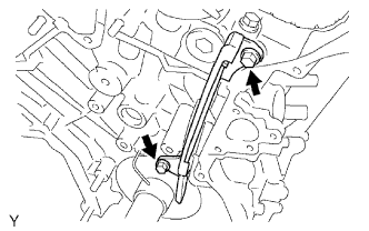
Install the No. 1 chain vibration damper with the 2 bolts.
- Torque:
- 19 N*m { 194 kgf*cm, 14 ft.*lbf }
-
-
INSTALL CAMSHAFT TIMING SPROCKET
-
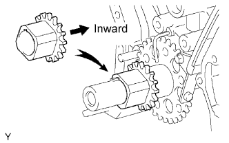
Align the timing gear set key with the key groove of the timing gear.
-
Install the timing gear onto the crankshaft, facing the gear side inward.
-
-
INSTALL CHAIN TENSIONER SLIPPER
-
INSTALL NO. 1 CHAIN TENSIONER
-
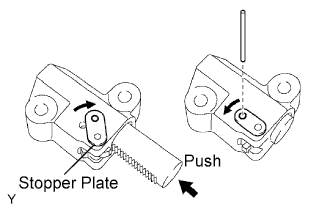
While rotating the stopper plate of the tensioner clockwise, push in the plunger of the tensioner as shown in the illustration.
-
While rotating the stopper plate of the tensioner counterclockwise, insert a pin of φ3.5 mm (0.138 in.) into the holes in the stopper plate and tensioner to fix the stopper plate.
-
Install the chain tensioner with the 2 bolts.
- Torque:
- 10 N*m { 102 kgf*cm, 7 ft.*lbf }
-
-
INSTALL CHAIN
-
Set the No. 1 cylinder to TDC/compression.
-
Align the timing marks of the camshaft timing gears and bearing caps.
-
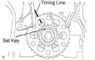
Using the crankshaft pulley set bolt, turn the crankshaft to align the crankshaft set key with the timing line of the cylinder block.
-
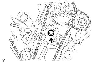
-
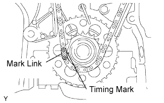
Align the mark link (yellow) with the timing mark of the crankshaft timing gear.
-
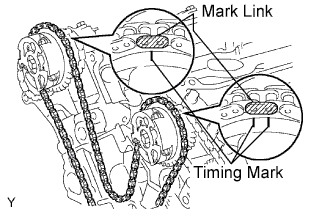
Align the mark links (orange) with the timing marks of the camshaft timing gears, and install the chain.
-
-
INSTALL NO. 2 CHAIN VIBRATION DAMPER
-
Install the 2 No. 2 chain vibration dampers.
-
-
INSTALL NO. 1 IDLE GEAR
-
Apply a light coat of engine oil to rotating surface of the No. 1 idle gear shaft.
-
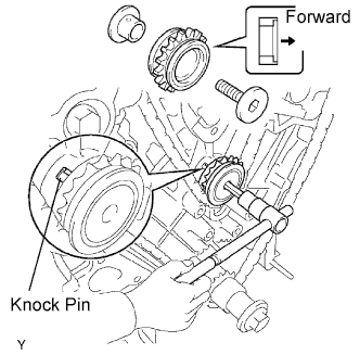
Temporarily install the No. 1 idle gear shaft and idle gear with the No. 2 idle gear shaft while aligning the knock pin of the No. 1 idle gear shaft with the knock pin groove of the cylinder block.
Note
Be careful of the idle gear direction.
-
Using a 10 mm hexagon wrench, tighten the No. 2 idle gear shaft.
- Torque:
- 60 N*m { 612 kgf*cm, 44 ft.*lbf }
-
Remove the pin from the chain tensioner.
-
-
INSTALL TIMING CHAIN COVER
-
Remove any old packing (FIPG) material and be careful not to drop any oil on the contact surfaces of the timing chain cover, cylinder head and cylinder block.
-
Install a new O-ring to the LH cylinder head as shown in the illustration.
-
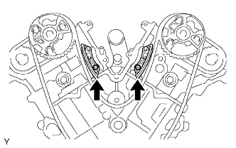
Apply seal packing to the 4 locations as shown in the illustration.
Seal packing Toyota Genuine Seal Packing Black, Three Bond 1207B or equivalent Standard seal diameter 3 to 4 mm (0.12 to 0.16 in.) -
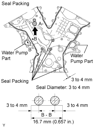
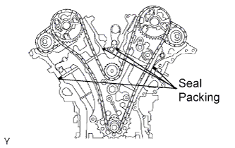
Apply a continuous line of seal packing to the timing chain cover as shown in the illustration.
Seal packing Water pump part: Toyota Genuine Seal Packing 1282B, Three Bond 1282B or equivalent Other part: Toyota Genuine Seal Packing Black, Three Bond 1207B or equivalent Standard seal diameter 3 to 4 mm (0.12 to 0.16 in.) Note
-
Install the timing chain cover within 3 minutes after applying seal packing. After installing it, timing chain cover bolts and nuts must be tightened within 15 minutes. Otherwise the seal packing must be removed and reapplied.
-
Do not apply seal packing to the "A" position.
-
-
Engage the spline teeth of the oil pump drive rotor with the large teeth of the crankshaft timing gear, and slide the timing chain cover.
-
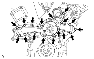
Install the timing chain cover with the 15 bolts and 2 nuts. Uniformly tighten the bolts and nuts in several passes.
- Torque:
- 23 N*m { 235 kgf*cm, 17 ft.*lbf }
Note
-
Pay attention not to wrap the chain and slipper over the timing chain cover seal line.
-
After installing the timing chain cover, install the water pump within 15 minutes.
Tech Tips
Each bolt length is as follows.
A: 25 mm (0.98 in.)
B: 55 mm (2.17 in.)
-
-
INSTALL WATER PUMP
-
Install a new gasket and the water pump with the 17 bolts.
- Torque:
- 9.0 N*m { 92 kgf*cm, 80 in.*lbf, for 10 mm (0.39 in.) head }
- 23 N*m { 235 kgf*cm, 17 ft.*lbf, for 12 mm (0.47 in.) head }
-
-
INSTALL NO. 1 OIL PAN
-
Remove any old packing (FIPG) material and be careful not to drop any oil on the contact surfaces of the cylinder block, rear oil seal retainer and oil pan.
-
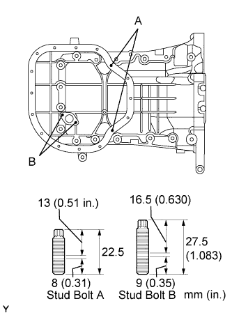
Install the 4 stud bolts.
- Torque:
- 4.0 N*m { 41 kgf*cm, 35 in.*lbf }
-
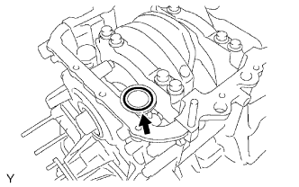
Install a new O-ring to the oil pump.
-
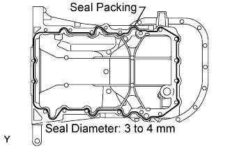
Apply a continuous line of seal packing to the oil pan as shown in the illustration.
Seal packing Toyota Genuine Seal Packing Black, Three Bond 1207B or equivalent Standard seal diameter 3 to 4 mm (0.12 to 0.16 in.) Note
Install the oil pan within 3 minutes after applying seal packing. After installing it, oil pan bolts and nuts must be tightened within 15 minutes. Otherwise the seal packing must be removed and reapplied.
-
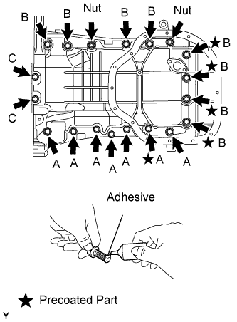
Install the oil pan with the 17 bolts and 2 nuts. Uniformly tighten the bolts and nuts in several passes.
- Torque:
- 21 N*m { 214 kgf*cm, 15 ft.*lbf, for bolt A, B and nut }
- 9.0 N*m { 92 kgf*cm, 80 in.*lbf, for bolt C }
Tech Tips
Each bolt length is as follows.
A: 25 mm (0.98 in.)
B: 40 mm (1.57 in.)
C: 14 mm (0.55 in.)
Note
The bolts indicated by stars in the illustration are precoated parts. When reusing them, apply adhesive to 2 or 3 threads before installation.
Adhesive Toyota Genuine Adhesive 1324, Three Bond 1324 or equivalent
-
-
INSTALL OIL STRAINER
-
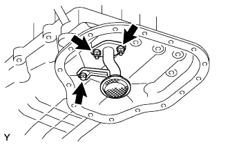
Install a new gasket and the oil strainer with the bolt and 2 nuts.
- Torque:
- 9.0 N*m { 92 kgf*cm, 80 in.*lbf }
-
-
INSTALL NO. 2 OIL PAN
-
Remove any old packing (FIPG) material and be careful not to drop any oil on the contact surfaces of the No. 2 oil pan and No. 1 oil pan.
-
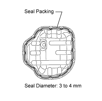
Apply a continuous line of seal packing as shown in the illustration.
Seal packing Toyota Genuine Seal Packing Black, Three Bond 1207B or equivalent Standard seal diameter 3 to 4 mm (0.12 to 0.16 in.) Note
Install the oil pan No. 2 within 3 minutes after applying seal packing. After installing it, No. 2 oil pan bolts and nuts must be tightened within 15 minutes. Otherwise the seal packing must be removed and reapplied.
-
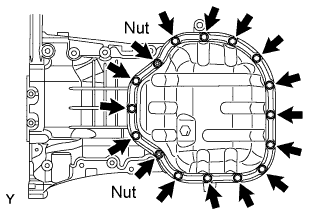
Install the No. 2 oil pan with the 14 bolts and 2 nuts. Uniformly tighten the bolts and nuts in several passes.
- Torque:
- 9.0 N*m { 92 kgf*cm, 80 in.*lbf }
-
-
INSTALL OIL PAN DRAIN PLUG
-
Install the drain plug with a new gasket.
- Torque:
- 40 N*m { 408 kgf*cm, 30 ft.*lbf }
-
-
INSTALL CRANKSHAFT PULLEY
-
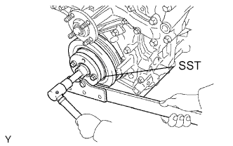
Using SST, install the pulley set bolt.
- SST
- 09213-54015 ( 91651-60855 )
- 09330-00021
- Torque:
- 250 N*m { 2,549 kgf*cm, 184 ft.*lbf }
-
-
SET NO. 1 CYLINDER TO TDC/COMPRESSION
-
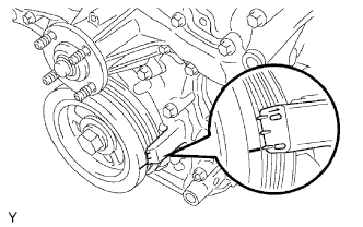
Turn the crankshaft pulley, and align its groove with the timing mark "0" of the timing chain cover.
-
Check that the timing marks of the camshaft timing gears are aligned with the timing marks of the bearing cap as shown in the illustration.
If not, turn the crankshaft 1 revolution (360°) and align the timing marks as described above.
-
-
INSPECT VALVE CLEARANCE
-
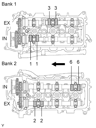
Check the valves indicated in the illustration.
-
Using a feeler gauge, measure the clearance between the valve lifter and camshaft.
Standard valve clearance (Cold) Item Specified Condition Intake 0.15 to 0.25 mm (0.006 to 0.010 in.) Exhaust 0.29 to 0.39 mm (0.011 to 0.015 in.) Tech Tips
Write down valve clearance measurements that are not within the specified range. They will be used later to determine the required replacement valve lifter.
-
-
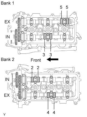
Turn the crankshaft 2/3 of a revolution (240°), and check the valves indicated in the illustration.
-
Using a feeler gauge, measure the clearance between the valve lifter and camshaft.
Standard valve clearance (Cold) Item Specified Condition Intake 0.15 to 0.25 mm (0.006 to 0.010 in.) Exhaust 0.29 to 0.39 mm (0.011 to 0.015 in.) -
Write down valve clearance measurements that are not within the specified range. They will be used later to determine the required replacement valve lifter.
-
-
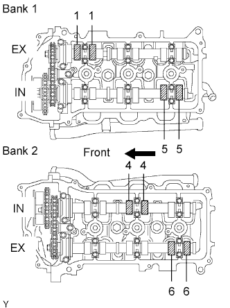
Turn the crankshaft 2/3 of a revolution (240°), and check the valves indicated in the illustration.
-
Using a feeler gauge, measure the clearance between the valve lifter and camshaft.
Standard valve clearance (Cold) Item Specified Condition Intake 0.15 to 0.25 mm (0.006 to 0.010 in.) Exhaust 0.29 to 0.39 mm (0.011 to 0.015 in.) -
Write down valve clearance measurements that are not within the specified range. They will be used later to determine the required replacement valve lifter.
-
-
-
INSTALL CYLINDER HEAD COVER RH
-
Remove any old packing (FIPG) material and be careful not to drop any oil on the contact surfaces of the cylinder head, timing chain cover and cylinder head cover.
-
Install the gasket to the cylinder head cover.
-
Apply seal packing to the cylinder head and timing chain cover as shown in the illustration.
Seal packing Toyota Genuine Seal Packing Black, Three Bond 1207B or equivalent Standard seal diameter 2 to 3 mm (0.08 to 0.12 in.) Note
Install the cylinder head cover within 3 minutes after applying seal packing. After installing it, cylinder head cover bolts and nuts must be tightened within 15 minutes. Otherwise the seal packing must be removed and reapplied.
-
Install the seal washers to the bolts.
-
Install the cylinder head cover with the 10 bolts and 2 nuts. Uniformly tighten the bolts and nuts in several passes.
- Torque:
- 10 N*m { 102 kgf*cm, 7 ft.*lbf, for bolt A }
- 9.0 N*m { 92 kgf*cm, 80 in.*lbf, for bolt B }
- 9.0 N*m { 92 kgf*cm, 80 in.*lbf, for nut }
-
-
INSTALL CYLINDER HEAD COVER LH
-
Remove any old packing (FIPG) material and be careful not to drop any oil on the contact surfaces of the cylinder head, timing chain cover and cylinder head cover.
-
Apply adhesive on the threads of the ventilation valve.
Adhesive Toyota Genuine Adhesive 1324, Three Bond 1324 or equivalent -
Install the ventilation valve to the cylinder head cover.
- Torque:
- 27 N*m { 275 kgf*cm, 20 ft.*lbf }
-
Install the gasket to the cylinder head cover.
-
Apply seal packing to the cylinder head and timing chain cover as shown in the illustration.
Seal packing Toyota Genuine Seal Packing Black, Three Bond 1207B or equivalent Standard seal diameter 2 to 3 mm (0.08 to 0.12 in.) Note
Install the cylinder head cover within 3 minutes after applying seal packing. After installing it, cylinder head cover bolts and nuts must be tightened within 15 minutes. Otherwise the seal packing must be removed and reapplied.
-
Install the seal washers to the bolts.
-
Install the cylinder head cover with the 10 bolts and 2 nuts. Uniformly tighten the bolts and nuts in several passes.
- Torque:
- 10 N*m { 102 kgf*cm, 7 ft.*lbf, for bolt A }
- 9.0 N*m { 92 kgf*cm, 80 in.*lbf, for bolt B }
- 9.0 N*m { 92 kgf*cm, 80 in.*lbf, for nut }
-
-
INSTALL OIL CONTROL VALVE FILTER
-
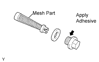
Check that no foreign objects on the mesh part of the 2 filters.
-
Install 2 new gaskets to each new plug.
-
Insert the filters to the plugs.
-
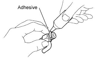
Apply adhesive to 2 or 3 threads of the plugs.
Adhesive Toyota Genuine Adhesive 1344, Three Bond 1344 or equivalent -
Install the plugs to each cylinder head.
- Torque:
- 62 N*m { 632 kgf*cm, 46 ft.*lbf }
-
-
INSTALL CRANKSHAFT POSITION SENSOR
-
Install the crankshaft position sensor with the bolt.
- Torque:
- 9.0 N*m { 92 kgf*cm, 80 in.*lbf }
-
-
INSTALL VVT SENSOR
-
Apply a light coat of engine oil to the O-ring of each VVT sensor.
-
Install the 2 VVT sensors with the 2 bolts.
- Torque:
- 8.0 N*m { 82 kgf*cm, 71 in.*lbf }
-
-
INSTALL CYLINDER BLOCK WATER DRAIN COCK
-
Apply adhesive to 2 or 3 threads of the drain cocks end.
Adhesive Toyota Genuine Adhesive 1324, Three Bond 1324 or equivalent -
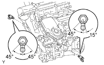
After applying the specified torque, rotate the drain cocks clockwise as shown in the illustration.
- Torque:
- 25 N*m { 255 kgf*cm, 18 ft.*lbf }
Note
-
Do not rotate the drain cocks more than 1 revolution (360°) after tightening the drain cocks with the specified torque.
-
Do not loosen the drain cocks after setting them correctly.
-
-
INSTALL OIL DIPSTICK GUIDE
-
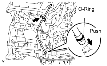
Install a new O-ring to the dipstick guide.
-
Apply a light coat of engine oil to the O-ring.
-
Push in the dipstick guide end into the guide hole of the oil pan.
-
Install the oil dipstick guide with the bolt.
- Torque:
- 9.0 N*m { 92 kgf*cm, 80 in.*lbf }
-
-
INSTALL NO. 2 ENGINE HANGER
-
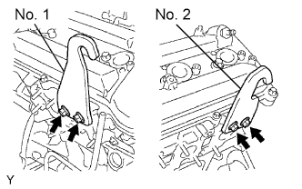
Install the engine hanger with the 2 bolts.
- Torque:
- 33 N*m { 336 kgf*cm, 24 ft.*lbf }
-
-
INSTALL NO.1 ENGINE HANGER
-
Install the engine hanger with the 2 bolts.
- Torque:
- 33 N*m { 336 kgf*cm, 24 ft.*lbf }
-