СИСТЕМА SFI, Diagnostic DTC:P0327, P0328, P0332, P0333
| DTC Code | DTC Name |
|---|---|
| P0327 | Knock Sensor 1 Circuit Low Input (Bank 1 or Single Sensor) |
| P0328 | Knock Sensor 1 Circuit High Input (Bank 1 or Single Sensor) |
| P0332 | Knock Sensor 2 Circuit Low Input (Bank 2) |
| P0333 | Knock Sensor 2 Circuit High Input (Bank 2) |
DESCRIPTION
A flat type knock sensor (non-resonant type) can detect vibrations in a wide band of frequency (6 kHz to 15 kHz).
The sensor, located on the cylinder block, detects spark knocks. When a spark knock occurs, the knock sensor picks up vibrations in a specific frequency range. When the ECM detects signal voltage in this frequency range, it retards the ignition timing to suppress the knocking. The ECM also senses background engine noise with the knock sensor and uses this noise to check for faults in the sensor.
| DTC No. | DTC Detection Condition | Trouble Area |
|---|---|---|
| P0327 P0332 |
Output voltage of knock sensor 1 or 2 is 0.5 V or less (1 trip detection logic) |
|
| P0328 P0333 |
Output voltage of knock sensor 1 or 2 is 4.5 V or more (1 trip detection logic) |
|
-
-
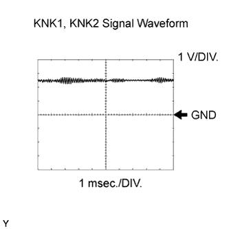
Reference: Inspect using an oscilloscope.
The correct waveform is as shown.
Item Content Symbols (Terminal No.) KNK1 (E16-29) - EKNK (E16-28)
KNK2 (E16-21) - EKN2 (E16-20)
Tool Setting 0.01 to 10 V/DIV., 0.01 to 10 msec./DIV. Condition Engine speed maintained at 4,000 rpm after warming up engine
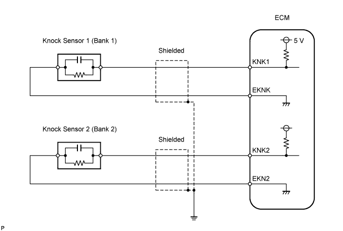
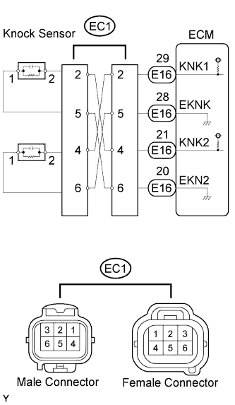
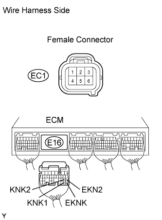
WIRING DIAGRAM
INSPECTION PROCEDURE
Tech Tips
-
DTC P0327 and P0328 are for the bank 1 knock sensor circuit.
-
DTC P0332 and P0333 are for the bank 2 knock sensor circuit.
-
Read freeze frame data using the intelligent tester. Freeze frame data records the engine conditions when a malfunction is detected. When troubleshooting, freeze frame data can help determine if the vehicle was running or stopped, if the engine was warmed up or not, if the air fuel ratio was lean or rich, and other data from the time the malfunction occurred.
PROCEDURE
-
READ OUTPUT DTC (CHECK KNOCK SENSOR CIRCUIT)
-
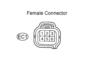
Disconnect the EC1 connector.
-
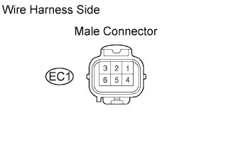
Using lead wires, connect the EC1 connectors as follows.
Male Connector - Female Connector Terminal 2 - Terminal 4 Terminal 5 - Terminal 6 Terminal 4 - Terminal 2 Terminal 6 - Terminal 5 -
Warm up the engine.
-
Race the engine at 3,000 rpm for 10 seconds or more.
-
Check for DTCs.
Result Display Proceed to DTC is same as when vehicle brought in (for example, P0327 and P0328 are output again, or P0332 and P0333 are output again) A DTC is different from when vehicle brought in (for example, P0327 and P0328 are output at first, but then P0332 and P0333 are output, or vice versa) B
B 
INSPECT KNOCK SENSOR Click here
A 
-
-
CHECK WIRE HARNESS (EC1 CONNECTOR - ECM)
-
Disconnect the EC1 connector.
-
Disconnect the E16 ECM connector.
-
Measure the resistance of the wire harness side connectors.
Standard resistance Tester Connection Specified Condition EC1 female connector 2 - E16-29 (KNK1) Below 1 Ω EC1 female connector 5 - E16-28 (EKNK) Below 1 Ω EC1 female connector 4 - E16-21 (KNK2) Below 1 Ω EC1 female connector 6 - E16-20 (EKN2) Below 1 Ω EC1 female connector 2 or E16-29 (KNK1) - Body ground 10 kΩ or higher EC1 female connector 5 or E16-28 (EKNK) - Body ground 10 kΩ or higher EC1 female connector 4 or E16-21 (KNK2) - Body ground 10 kΩ or higher EC1 female connector 6 or E16-20 (EKN2) - Body ground 10 kΩ or higher
NG 
REPAIR OR REPLACE HARNESS AND CONNECTOR
OK
-
-
CHECK ECM (KNK1, KNK2 VOLTAGE)
-
Disconnect the EC1 ECM connector.
-
Turn the ignition switch ON.
-
Measure the voltage of the EC1 female connector.
Standard voltage Tester Connection Specified Condition EC1 female connector 2 - EC1 female connector 5 4.5 to 5.5 V EC1 female connector 4 - EC1 female connector 6 4.5 to 5.5 V
NG
REPLACE ECM
OK
-
-
CHECK FOR INTERMITTENT PROBLEMS
Note
The fault may be intermittent. Check the harness and connectors carefully, and retest.
NEXT 
END
-
INSPECT KNOCK SENSOR
-
Disconnect the EC1 connector.
-
Measure the resistance of the EC1 male connector.
Standard resistance Tester Connection Specified Condition EC1 male connector 2 - 5 120 to 280 kΩ EC1 male connector 4 - 6 120 to 280 kΩ
OK
CHECK FOR INTERMITTENT PROBLEMS
NG
-
-
CHECK WIRE HARNESS (EB2 CONNECTOR - KNOCK SENSOR)
Tech Tips
-
If DTC P0327 or P0328 has changed to P0332 or P0333, check the knock sensor circuit on the bank 1 side.
-
If DTC P0332 or P0333 has changed to P0327 or P0328, check the knock sensor circuit on the bank 2 side.
-
Disconnect the EC1 connector.
-
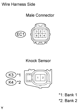
Disconnect the K3 and K4 knock sensor connectors.
-
Measure the resistance of the wire harness side connectors.
Standard resistance Terminal No. Specified Condition EC1 male connector 2 - K3-2 Below 1 Ω EC1 male connector 5 - K3-1 Below 1 Ω EC1 male connector 4 - K4-2 Below 1 Ω EC1 male connector 6 - K4-1 Below 1 Ω EC1 male connector 2 or K3-2 - Body ground 10 kΩ or higher EC1 male connector 5 or K3-1 - Body ground 10 kΩ or higher EC1 male connector 4 or K4-2 - Body ground 10 kΩ or higher EC1 male connector 6 or K4-1 - Body ground 10 kΩ or higher
NG
REPAIR OR REPLACE HARNESS AND CONNECTOR
OK
REPLACE KNOCK SENSOR
-